FLEX CIRCUITS DESIGN GUIDE
Minco Flex Circuits Design Guide - BiS Sistem
Minco Flex Circuits Design Guide - BiS Sistem
- No tags were found...
You also want an ePaper? Increase the reach of your titles
YUMPU automatically turns print PDFs into web optimized ePapers that Google loves.
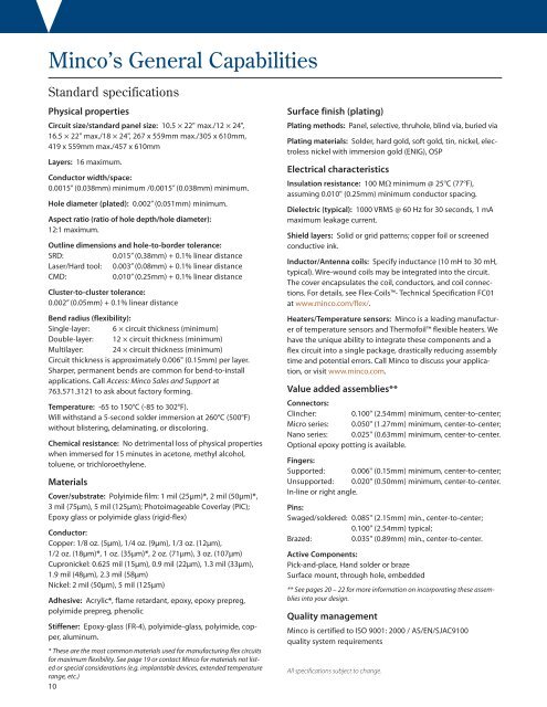
Minco’s General Capabilities<br />
Standard specifications<br />
Physical properties<br />
Circuit size/standard panel size: 10.5 × 22" max./12 × 24",<br />
16.5 × 22" max./18 × 24", 267 x 559mm max./305 x 610mm,<br />
419 x 559mm max./457 x 610mm<br />
Layers: 16 maximum.<br />
Conductor width/space:<br />
0.0015” (0.038mm) minimum /0.0015” (0.038mm) minimum.<br />
Hole diameter (plated): 0.002” (0.051mm) minimum.<br />
Aspect ratio (ratio of hole depth/hole diameter):<br />
12:1 maximum.<br />
Outline dimensions and hole-to-border tolerance:<br />
SRD:<br />
0.015” (0.38mm) + 0.1% linear distance<br />
Laser/Hard tool: 0.003” (0.08mm) + 0.1% linear distance<br />
CMD:<br />
0.010” (0.25mm) + 0.1% linear distance<br />
Cluster-to-cluster tolerance:<br />
0.002” (0.05mm) + 0.1% linear distance<br />
Bend radius (flexibility):<br />
Single-layer: 6 × circuit thickness (minimum)<br />
Double-layer: 12 × circuit thickness (minimum)<br />
Multilayer: 24 × circuit thickness (minimum)<br />
Circuit thickness is approximately 0.006" (0.15mm) per layer.<br />
Sharper, permanent bends are common for bend-to-install<br />
applications. Call Access: Minco Sales and Support at<br />
763.571.3121 to ask about factory forming.<br />
Temperature: -65 to 150°C (-85 to 302°F).<br />
Will withstand a 5-second solder immersion at 260°C (500°F)<br />
without blistering, delaminating, or discoloring.<br />
Chemical resistance: No detrimental loss of physical properties<br />
when immersed for 15 minutes in acetone, methyl alcohol,<br />
toluene, or trichloroethylene.<br />
Materials<br />
Cover/substrate: Polyimide film: 1 mil (25μm)*, 2 mil (50μm)*,<br />
3 mil (75μm), 5 mil (125μm); Photoimageable Coverlay (PIC);<br />
Epoxy glass or polyimide glass (rigid-flex)<br />
Conductor:<br />
Copper: 1/8 oz. (5μm), 1/4 oz. (9μm), 1/3 oz. (12μm),<br />
1/2 oz. (18μm)*, 1 oz. (35μm)*, 2 oz. (71μm), 3 oz. (107μm)<br />
Cupronickel: 0.625 mil (15μm), 0.9 mil (22μm), 1.3 mil (33μm),<br />
1.9 mil (48μm), 2.3 mil (58μm)<br />
Nickel: 2 mil (50μm), 5 mil (125μm)<br />
Adhesive: Acrylic*, flame retardant, epoxy, epoxy prepreg,<br />
polyimide prepreg, phenolic<br />
Stiffener: Epoxy-glass (FR-4), polyimide-glass, polyimide, copper,<br />
aluminum.<br />
* These are the most common materials used for manufacturing flex circuits<br />
for maximum flexibility. See page 19 or contact Minco for materials not listed<br />
or special considerations (e.g. implantable devices, extended temperature<br />
range, etc.)<br />
10<br />
Surface finish (plating)<br />
Plating methods: Panel, selective, thruhole, blind via, buried via<br />
Plating materials: Solder, hard gold, soft gold, tin, nickel, electroless<br />
nickel with immersion gold (ENIG), OSP<br />
Electrical characteristics<br />
Insulation resistance: 100 MΩ minimum @ 25°C (77°F),<br />
assuming 0.010" (0.25mm) minimum conductor spacing.<br />
Dielectric (typical): 1000 VRMS @ 60 Hz for 30 seconds, 1 mA<br />
maximum leakage current.<br />
Shield layers: Solid or grid patterns; copper foil or screened<br />
conductive ink.<br />
Inductor/Antenna coils: Specify inductance (10 mH to 30 mH,<br />
typical). Wire-wound coils may be integrated into the circuit.<br />
The cover encapsulates the coil, conductors, and coil connections.<br />
For details, see Flex-Coils- Technical Specification FC01<br />
at www.minco.com/flex/.<br />
Heaters/Temperature sensors: Minco is a leading manufacturer<br />
of temperature sensors and Thermofoil flexible heaters. We<br />
have the unique ability to integrate these components and a<br />
flex circuit into a single package, drastically reducing assembly<br />
time and potential errors. Call Minco to discuss your application,<br />
or visit www.minco.com.<br />
Value added assemblies**<br />
Connectors:<br />
Clincher:<br />
0.100" (2.54mm) minimum, center-to-center;<br />
Micro series: 0.050" (1.27mm) minimum, center-to-center;<br />
Nano series: 0.025" (0.63mm) minimum, center-to-center.<br />
Optional epoxy potting is available.<br />
Fingers:<br />
Supported: 0.006" (0.15mm) minimum, center-to-center;<br />
Unsupported: 0.020" (0.50mm) minimum, center-to-center.<br />
In-line or right angle.<br />
Pins:<br />
Swaged/soldered: 0.085" (2.15mm) min., center-to-center;<br />
0.100" (2.54mm) typical;<br />
Brazed:<br />
0.035" (0.89mm) min., center-to-center.<br />
Active Components:<br />
Pick-and-place, Hand solder or braze<br />
Surface mount, through hole, embedded<br />
** See pages 20 – 22 for more information on incorporating these assemblies<br />
into your design.<br />
Quality management<br />
Minco is certified to ISO 9001: 2000 / AS/EN/SJAC9100<br />
quality system requirements<br />
All specifications subject to change.


