FLEX CIRCUITS DESIGN GUIDE
Minco Flex Circuits Design Guide - BiS Sistem
Minco Flex Circuits Design Guide - BiS Sistem
- No tags were found...

You also want an ePaper? Increase the reach of your titles
YUMPU automatically turns print PDFs into web optimized ePapers that Google loves.
Minco’s General Capabilities<br />
Conductor width nomograph<br />
The nomograph on the facing page will help you determine the<br />
maximum allowable current capacity (in amperes) of a conductor.<br />
Reprinted from IPC-2221 (and MIL-STD-2118), the nomograph<br />
shows current for various conductor thicknesses, width,<br />
and temperature rises.<br />
Using the nomograph<br />
1. Locate the width of the conductor on the left side of the<br />
bottom chart.<br />
2. Move right horizontally, until you intersect the line of the<br />
appropriate conductor thickness. Move down vertically to<br />
the bottom of the chart to determine the cross-sectional area<br />
of the conductor.<br />
3. Move up vertically, until you intersect the line of the appropriate<br />
allowable temperature rise. This is the increase in temperature<br />
of the current-carrying conductor. Conductor temperature<br />
should not exceed 105°C. For example, if the ambient<br />
temperature might reach 80°C, the temperature rise<br />
above ambient of the conductor should be less than 25°C<br />
(105°C - 80°C). In this case use the 20°C curve.<br />
4. Move left horizontally to the left side of the chart to<br />
determine the maximum allowable current.<br />
Reverse the order of these steps to calculate required conductor<br />
width for a given current.<br />
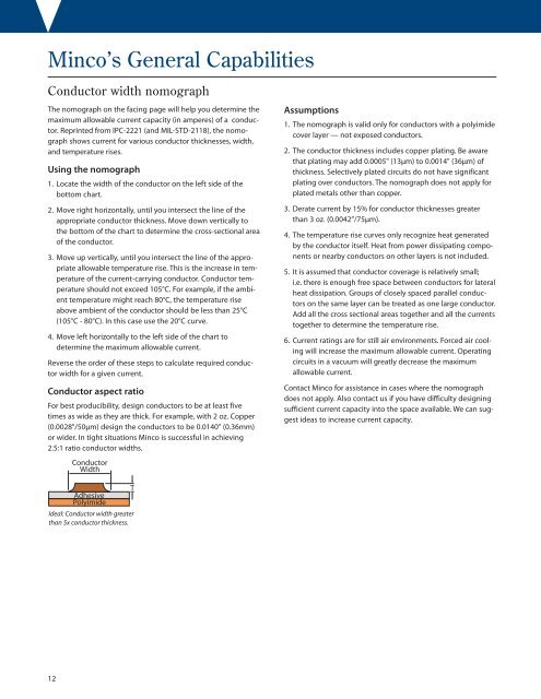
Conductor aspect ratio<br />
For best producibility, design conductors to be at least five<br />
times as wide as they are thick. For example, with 2 oz. Copper<br />
(0.0028"/50μm) design the conductors to be 0.0140" (0.36mm)<br />
or wider. In tight situations Minco is successful in achieving<br />
2.5:1 ratio conductor widths.<br />
Conductor<br />
Width<br />
Assumptions<br />
1. The nomograph is valid only for conductors with a polyimide<br />
cover layer — not exposed conductors.<br />
2. The conductor thickness includes copper plating. Be aware<br />
that plating may add 0.0005" (13μm) to 0.0014" (36μm) of<br />
thickness. Selectively plated circuits do not have significant<br />
plating over conductors. The nomograph does not apply for<br />
plated metals other than copper.<br />
3. Derate current by 15% for conductor thicknesses greater<br />
than 3 oz. (0.0042”/75μm).<br />
4. The temperature rise curves only recognize heat generated<br />
by the conductor itself. Heat from power dissipating components<br />
or nearby conductors on other layers is not included.<br />
5. It is assumed that conductor coverage is relatively small;<br />
i.e. there is enough free space between conductors for lateral<br />
heat dissipation. Groups of closely spaced parallel conductors<br />
on the same layer can be treated as one large conductor.<br />
Add all the cross sectional areas together and all the currents<br />
together to determine the temperature rise.<br />
6. Current ratings are for still air environments. Forced air cooling<br />
will increase the maximum allowable current. Operating<br />
circuits in a vacuum will greatly decrease the maximum<br />
allowable current.<br />
Contact Minco for assistance in cases where the nomograph<br />
does not apply. Also contact us if you have difficulty designing<br />
sufficient current capacity into the space available. We can suggest<br />
ideas to increase current capacity.<br />
T<br />
Adhesive<br />
Polyimide<br />
Ideal: Conductor width greater<br />
than 5x conductor thickness.<br />
12