FLEX CIRCUITS DESIGN GUIDE
Minco Flex Circuits Design Guide - BiS Sistem
Minco Flex Circuits Design Guide - BiS Sistem
- No tags were found...

You also want an ePaper? Increase the reach of your titles
YUMPU automatically turns print PDFs into web optimized ePapers that Google loves.
Benefits of Flex Circuits<br />
High reliability<br />
Repeatable installation<br />
Compared to discrete wiring, or ribbon cable, a flex circuit offers<br />
a customized repeatable routing path within your assembly. This<br />
gives you dependability where you need it. A flex circuit’s<br />
longevity can reduce service calls.<br />
Harsh environments<br />
Standard practice for flex boards is to cover the conductors with<br />
polyimide. This dielectric layer protects your circuits far beyond<br />
the capability of simple soldermask. Other base and cover<br />
materials are available for a broad range of ambient conditions.<br />
Long duty cycles<br />
By design, a flex circuit can be made very thin, yet robust<br />
enough to withstand thousands to millions of flexing cycles<br />
while carrying signal and power without a break.<br />
High vibration<br />
Under vibration and/or high acceleration, a flex circuit’s ductility<br />
and low mass will reduce the impact upon itself and solder<br />
joints. By contrast, a PCB’s higher vibrational mass will increase<br />
stresses upon itself, components and solder joints.<br />
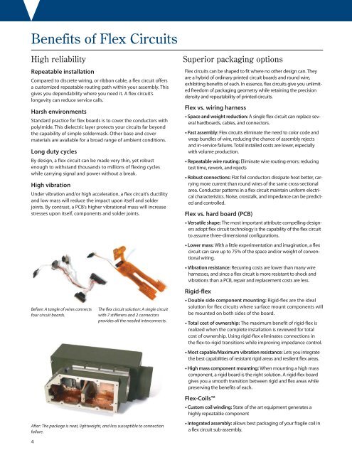
Before: A tangle of wires connects<br />
four circuit boards.<br />
The flex circuit solution: A single circuit<br />
with 7 stiffeners and 2 connectors<br />
provides all the needed interconnects.<br />
After: The package is neat, lightweight, and less susceptible to connection<br />
failure.<br />
Superior packaging options<br />
Flex circuits can be shaped to fit where no other design can. They<br />
are a hybrid of ordinary printed circuit boards and round wire,<br />
exhibiting benefits of each. In essence, flex circuits give you unlimited<br />
freedom of packaging geometry while retaining the precision<br />
density and repeatability of printed circuits.<br />
Flex vs. wiring harness<br />
• Space and weight reduction: A single flex circuit can replace several<br />
hardboards, cables, and connectors.<br />
• Fast assembly: Flex circuits eliminate the need to color code and<br />
wrap bundles of wire, reducing the chance of assembly rejects<br />
and in-service failures. Total installed costs are lower, especially<br />
with volume production.<br />
• Repeatable wire routing: Eliminate wire routing errors; reducing<br />
test time, rework, and rejects<br />
• Robust connections: Flat foil conductors dissipate heat better, carrying<br />
more current than round wires of the same cross-sectional<br />
area. Conductor patterns in a flex circuit maintain uniform electrical<br />
characteristics. Noise, crosstalk, and impedance can be predicted<br />
and controlled.<br />
Flex vs. hard board (PCB)<br />
• Versatile shape: The most important attribute compelling designers<br />
adopt flex circuit technology is the capability of the flex circuit<br />
to assume three-dimensional configurations.<br />
• Lower mass: With a little experimentation and imagination, a flex<br />
circuit can save up to 75% of the space and/or weight of conventional<br />
wiring.<br />
• Vibration resistance: Recurring costs are lower than many wire<br />
harnesses, and since a flex circuit is more resistant to shock and<br />
vibrations than a PCB, repair and replacement costs are less.<br />
Rigid-flex<br />
• Double side component mounting: Rigid-flex are the ideal<br />
solution for flex circuits where surface mount components will<br />
be mounted on both sides of the board.<br />
• Total cost of ownership: The maximum benefit of rigid-flex is<br />
realized when the complete installation is reviewed for total<br />
cost of ownership. Using rigid-flex eliminates connections in<br />
the flex-to-rigid transitions while improving impedance control.<br />
• Most capable/Maximum vibration resistance: Lets you integrate<br />
the best capabilities of resistant rigid areas and resilient flex areas.<br />
• High mass component mounting: When mounting a high mass<br />
component, a rigid board is the right solution. A rigid-flex board<br />
gives you a smooth transition between rigid and flex areas while<br />
preserving the benefits of each.<br />
Flex-Coils<br />
• Custom coil winding: State of the art equipment generates a<br />
highly repeatable component<br />
• Integrated assembly: allows best packaging of your fragile coil in<br />
a flex circuit sub-assembly.<br />
4