FLEX CIRCUITS DESIGN GUIDE
Minco Flex Circuits Design Guide - BiS Sistem
Minco Flex Circuits Design Guide - BiS Sistem
- No tags were found...

You also want an ePaper? Increase the reach of your titles
YUMPU automatically turns print PDFs into web optimized ePapers that Google loves.
Standard Design Recommendations<br />
Design differences and special considerations<br />
Define circuit parameters by application<br />
It may be helpful to use a paper template to represent the circuit.<br />
Experiment with bending and forming the template to optimize<br />
shape and fit. When designing the final shape, consider how the<br />
circuits will lay out on a processing panel (“nesting”). The greater<br />
the number of circuits per panel, the lower the cost.<br />
Another consideration concerns rigid-flex. While Minco is capable<br />
of building a traditional rigid-flex board for you it may not<br />
be your best choice. Multilayer or stiffened flex boards may be<br />
able to meet your requirements for component and board<br />
mounting at reduced cost.<br />
Flex circuit vs. hardboards<br />
Designing a flex circuit is only one step away from designing a<br />
hardboard. The most important design difference to keep in mind<br />
is the three-dimensionality of a flex circuit. Creative bending and<br />
flexing can save space and layers. Other important differences:<br />
• Flex circuits both require and permit looser tolerances than<br />
hardboards.<br />
• Because arms can flex, design them slightly longer than<br />
required.<br />
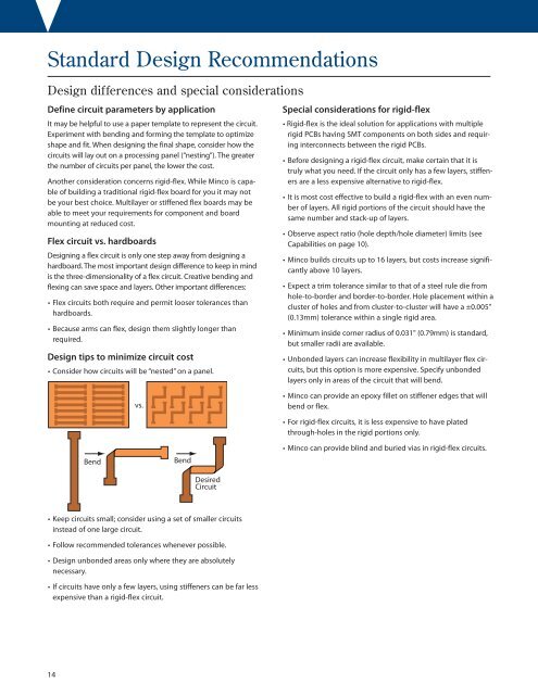
Design tips to minimize circuit cost<br />
• Consider how circuits will be “nested” on a panel.<br />
Special considerations for rigid-flex<br />
• Rigid-flex is the ideal solution for applications with multiple<br />
rigid PCBs having SMT components on both sides and requiring<br />
interconnects between the rigid PCBs.<br />
• Before designing a rigid-flex circuit, make certain that it is<br />
truly what you need. If the circuit only has a few layers, stiffeners<br />
are a less expensive alternative to rigid-flex.<br />
• It is most cost effective to build a rigid-flex with an even number<br />
of layers. All rigid portions of the circuit should have the<br />
same number and stack-up of layers.<br />
• Observe aspect ratio (hole depth/hole diameter) limits (see<br />
Capabilities on page 10).<br />
• Minco builds circuits up to 16 layers, but costs increase significantly<br />
above 10 layers.<br />
• Expect a trim tolerance similar to that of a steel rule die from<br />
hole-to-border and border-to-border. Hole placement within a<br />
cluster of holes and from cluster-to-cluster will have a ±0.005"<br />
(0.13mm) tolerance within a single rigid area.<br />
• Minimum inside corner radius of 0.031" (0.79mm) is standard,<br />
but smaller radii are available.<br />
• Unbonded layers can increase flexibility in multilayer flex circuits,<br />
but this option is more expensive. Specify unbonded<br />
layers only in areas of the circuit that will bend.<br />
vs.<br />
• Minco can provide an epoxy fillet on stiffener edges that will<br />
bend or flex.<br />
Bend<br />
Bend<br />
• For rigid-flex circuits, it is less expensive to have plated<br />
through-holes in the rigid portions only.<br />
• Minco can provide blind and buried vias in rigid-flex circuits.<br />
Desired<br />
Circuit<br />
• Keep circuits small; consider using a set of smaller circuits<br />
instead of one large circuit.<br />
• Follow recommended tolerances whenever possible.<br />
• Design unbonded areas only where they are absolutely<br />
necessary.<br />
• If circuits have only a few layers, using stiffeners can be far less<br />
expensive than a rigid-flex circuit.<br />
14