FLEX CIRCUITS DESIGN GUIDE
Minco Flex Circuits Design Guide - BiS Sistem
Minco Flex Circuits Design Guide - BiS Sistem
- No tags were found...

You also want an ePaper? Increase the reach of your titles
YUMPU automatically turns print PDFs into web optimized ePapers that Google loves.
Minco’s General Capabilities<br />
Testing<br />
When specifying testing, consider your needs carefully. Overspecification<br />
can greatly increase circuit cost. Minco encourages<br />
electrical testing. It is required on all multilayer, rigid-flex, and<br />
factory-formed circuits that are fabricated to MIL-P 50884, and<br />
certain classes of IPC-6013.<br />
See the table below for information on Minco’s test capabilities.<br />
Minco can test for… Range of operation<br />
IPC-6013<br />
N.A.<br />
MIL-P-50884 conformance<br />
Complete dimensions Resolution: 4 decimal places<br />
Accuracy: 0.001” (0.025mm) +<br />
0.008% of linear distance<br />
Dielectric withstanding Up to 6000 V<br />
Electrical continuity 1 Ω to 10 k Ω; suggest 5 Ω<br />
Stimulus: 0.01 V to 5.0 V<br />
Ionic cleanliness<br />
.5 microgram/square cm<br />
NACL equivalent<br />
Insulation resistance 10 k Ω to 100 M Ω at 10 V to 250 VDC<br />
Suggest 100 M Ω at 100 VDC<br />
Thermal shock -70 to 200°C<br />
Moisture resistance Up to 98% relative humidity<br />
Plating thickness<br />
Down to 0.000001" (0.02μm)<br />
Flexibility<br />
0 to 999,999 flexes<br />
Microsections Viewed at up to 1000×<br />
Marking<br />
Minco can meet your marking requirements.<br />
Our legend marking system offers silkscreen-like printing using<br />
a durable white ink that meets IPC-TM-650 industry standards.<br />
This system allows us to incorporate date code and serial numbering,<br />
along with panel based marking, at the same time.<br />
We can also offer traditional epoxy ink hand stamp or silkscreen<br />
printing if an alternate color or legacy specification is required.<br />
Etched marking within the part is also an option. Stiffeners and<br />
covers may be marked with component mounting locations.<br />
Controlling impedance and electrical noise<br />
Predictable electrical characteristics make flex circuits an ideal<br />
choice for high-speed signal transmission. Uniform spacing<br />
between conductors and grounds, continuous shield layers,<br />
and repeatable geometries are features that help control<br />
impedance and reduce crosstalk. And with flex circuits, you can<br />
eliminate connectors and other transitions that contribute to<br />
signal attenuation.<br />
Minco can provide tight tolerances on line width, spacing, and<br />
distance to ground layers in order to meet your impedance<br />
requirements. Actual impedance will also depend on the circuit’s<br />
shape after installation.<br />
Contact Minco for advice on designing circuits to specific<br />
electrical characteristics.<br />
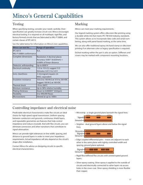
• Microstrip - a single ground plane beneath the signal lines.<br />
Signal<br />
Ground<br />
• Stripline - dual ground layers above and below the signal<br />
lines.<br />
Ground<br />
Signal<br />
Ground<br />
• Edge coupled differential pairs – traces are adjacent to each<br />
other in the same plane with tightly controlled width and<br />
spacing, ground plane optional.<br />
Signal<br />
Ground<br />
• Rigid-flex/stiffened flex circuits with uninterrupted ground<br />
layers.<br />
• Silver epoxy coating. Silver epoxy is applied to the outside of<br />
circuits and electrically connected to other layers via access<br />
holes in the cover coat. Silver epoxy shielding is more flexible<br />
than copper.<br />
11