FLEX CIRCUITS DESIGN GUIDE
Minco Flex Circuits Design Guide - BiS Sistem
Minco Flex Circuits Design Guide - BiS Sistem
- No tags were found...

You also want an ePaper? Increase the reach of your titles
YUMPU automatically turns print PDFs into web optimized ePapers that Google loves.
Value Added Design Options<br />
Terminations<br />
There are a variety of terminations for a flex circuit, and a variety<br />
of methods for applying these terminations.<br />
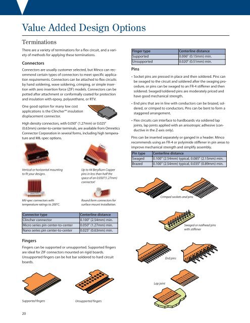
Connectors<br />
Connectors are usually customer selected, but Minco can recommend<br />
certain types of connectors to meet specific application<br />
requirements. Connectors can be attached to flex circuits<br />
by hand soldering, wave soldering, crimping, or simple insertion<br />
with zero insertion force (ZIF) models. Connectors can be<br />
potted after attachment or conformally coated for protection<br />
and insulation with epoxy, polyurethane, or RTV.<br />
One good option for many low cost<br />
applications is the Clincher insulation<br />
displacement connector.<br />
High density connectors, with 0.050" (1.27mm) or 0.025"<br />
(0.63mm) center-to-center terminals, are available from Omnetics<br />
Connector Corporation in several forms, including high temperature<br />
and MIL-spec options.<br />
Finger type<br />
Supported<br />
Unsupported<br />
Pins<br />
Centerline distance<br />
0.006" (0.15mm) min.<br />
0.020" (0.51mm) min.<br />
• Socket pins are pressed in place and then soldered. Pins can<br />
be swaged to the circuit and soldered after the swaging procedure,<br />
or pins can be swaged to an FR-4 stiffener and then<br />
soldered. Swaged/soldered pins are moderately priced and<br />
have good mechanical strength.<br />
• End pins that are in line with conductors can be brazed, soldered,<br />
or crimped to conductors. Pins can be bent to form a<br />
staggered arrangement.<br />
• Flex circuits can interface to hardboards via soldered lap<br />
joints, lap joints applied with an anisotropic adhesive (conductive<br />
in the Z-axis only).<br />
Pins can be inserted separately or ganged in a header. Minco<br />
recommends using an FR-4 or polyimide stiffener in pin areas to<br />
improve mechanical strength and simplify assembly.<br />
Pin type Centerline distance<br />
Swaged 0.100" (2.54mm) typical, 0.085" (2.15mm) min.<br />
Brazed 0.100" (2.54mm) typical, 0.035" (0.89mm) min.<br />
Vertical or horizontal mounting<br />
to fit your designs.<br />
Up to 44 Beryllium Copper<br />
pins in less than half the<br />
space of an 0.050"(1.27mm)<br />
connector!<br />
Mil-spec connectors with<br />
temperature ratings to 200°C.<br />
Round form connectors for<br />
surface mount installation.<br />
Crimped sockets and pins<br />
Connector type<br />
Clincher connector<br />
Micro series pin center-to-center<br />
Nano series pin center-to-center<br />
Centerline distance<br />
0.100" (2.54mm) min.<br />
0.050" (1.27mm) min.<br />
0.025" (0.63mm) min.<br />
Swaged or nailhead pins<br />
with stiffener<br />
Fingers<br />
Fingers can be supported or unsupported. Supported fingers<br />
are ideal for ZIF connectors mounted on rigid boards.<br />
Unsupported fingers can be hot bar soldered to hard circuit<br />
boards.<br />
End pins<br />
Lap joint<br />
Supported fingers<br />
Unsupported fingers<br />
20