

SATRONIC - Control boxes for oil burners
SATRONIC - Control boxes for oil burners
SATRONIC - Control boxes for oil burners

Create successful ePaper yourself
Turn your PDF publications into a flip-book with our unique Google optimized e-Paper software.
TECHNICAL FEATURES<br />
1. Flame detection<br />
The following types of flame detector can be used:<br />
- Ionisation electrode, where the mains supply provides a<br />
neutral earth connection. Suitable <strong>for</strong> gas <strong>burners</strong> (signal<br />
current from flame cannot be influenced by interference<br />
from ignition spark).<br />
- UV sensor type UVZ 780 red, suitable <strong>for</strong> gas, <strong>oil</strong> and dual<br />
fuel <strong>burners</strong>.<br />
- Infra-red flicker detector type IRD 820 and 1020 <strong>for</strong> all<br />
types of burner.<br />
The flame signal amplifier is adjusted to the the type of<br />
detector probe fitted by using the flame detector selection<br />
switch on the underside of the unit. If the IRD flicker detector<br />
is used, the selection switch must be adjusted to the "ION"<br />
position.<br />
Flame detection is only operational when the switch position<br />
selected corresponds to the type of detector probe<br />
connected.<br />
By optimally matching the amplifier to the detector probe,<br />
considerably longer signal transmission distances with less<br />
sensitivity to interference can be achieved.<br />
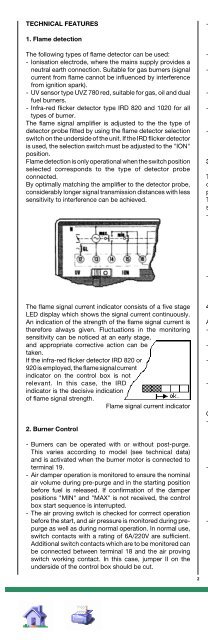
The flame signal current indicator consists of a five stage<br />
LED display which shows the signal current continuously.<br />
An indication of the strength of the flame signal current is<br />
there<strong>for</strong>e always given. Fluctuations in the monitoring<br />
sensitivity can be noticed at an early stage,<br />
and appropriate corrective action can be<br />
taken.<br />
If the infra-red flicker detector IRD 820 or<br />
920 is employed, the flame signal current<br />
indicator on the control box is not<br />
relevant. In this case, the IRD<br />
indicator is the decisive indication<br />
of flame signal strength.<br />
Flame signal current indicator<br />
2. Burner <strong>Control</strong><br />
- Burners can be operated with or without post-purge.<br />
This varies according to model (see technical data)<br />
and is activated when the burner motor is connected to<br />
terminal 19.<br />
- Air damper operation is monitored to ensure the nominal<br />
air volume during pre-purge and in the starting position<br />
be<strong>for</strong>e fuel is released. If confirmation of the damper<br />
positions "MIN" and "MAX" is not received, the control<br />
box start sequence is interrupted.<br />
- The air proving switch is checked <strong>for</strong> corrrect operation<br />
be<strong>for</strong>e the start, and air pressure is monitored during prepurge<br />
as well as during normal operation. In normal use,<br />
switch contacts with a rating of 6A/220V are sufficient.<br />
Additional switch contacts which are to be monitored can<br />
be connected between terminal 18 and the air proving<br />
switch working contact. In this case, jumper II on the<br />
underside of the control box should be cut.<br />
2<br />
- A separate connection <strong>for</strong> a pilot valve PV is provided,<br />
which is again closed at the end of the second safety<br />
interval. The heat output of the gas flow which is controlled<br />
by this valve must not exceed 120kW.<br />
- The terminal <strong>for</strong> the start valve SV must not be used when<br />
connecting the pilot valve PV.<br />
- Together with the start valve SV, a total of 3 power levels<br />
are available <strong>for</strong> use. The gas flow controlled by valves<br />
SV, V1 and V2 must lead to a common nozzle unit.<br />
- To determin the heating power of the gas flow controlled<br />
by the pilot- and start valve, EN 676 has to be consulted.<br />
- In addition to the built-in button with signal lamp, it is also<br />
possible to connect a remote lockout indicator and reset<br />
switch.<br />
- For monitoring of the ignition spark, link 1 on the base of<br />
the control box must be cut. In this case, flame detection<br />
is carried out by a UVZ 780 ultra-violet sensor.<br />
3. Safety<br />
The design and programme sequence employed in the<br />
control <strong>boxes</strong> in the TMG 740-3 series con<strong>for</strong>m to the<br />
presently applicable European standards and regulations.<br />
The following features exceed the requirements of most<br />
standards, and there<strong>for</strong>e ensure additional safety:<br />
- After a normal shutdown, the stray light test is started<br />
immediatly by the control box which directs an increased<br />
voltage to the UV sensor. The very important extinguishing<br />
function of the sensor can there<strong>for</strong>e be checked. If the fuel<br />
valve does not close correctly, or a sensor or amplifier<br />
malfunction occurs, shutdown and lockout take place<br />
after approx. 20 sec., even if the controlling thermostat<br />
is open.<br />
- The contacts responsible <strong>for</strong> the release of fuel are checked<br />
when the programme starts, to ensure that they have not<br />
become welded together.<br />
4. Mounting and Electrical Installation<br />
At the base:<br />
- 3 earth terminals, with an additional tag <strong>for</strong> the burner<br />
earth.<br />
- 3 neutral terminals, with a fixed internal through connection<br />
to the neutral input, terminal 8.<br />
- 2 separate slide-in plates and 4 fixed, threaded knockouts<br />
(PG 11 thread) as well as a wiring opening from below, to<br />
facilitate wiring of the base.<br />
- A keyed fit ensures that the wrong control box type cannot<br />
be fitted to the base. The corresponding control box<br />
designation is shown in lettering on the base.<br />
General:<br />
- Can be mounted in any position, insulated as per IP 44<br />
standard (unaffected by water spray). The control box and<br />
detector probes should not however be subjected to<br />
excessive vibration. With the UVZ 780 ultra-violet sensor,<br />
care should be taken to ensure that a good electrical<br />
contact to the burner exists via the metal flange.<br />
- If an ionisation electrode is used, appropriate protective<br />
measures are required in order to avoid contact with the<br />
electrode while installation work is being carried out.<br />
Trouble-free operation with this type of flame detection is<br />
not possible if a voltage of over 25 volts is measured<br />
between neutral and earth. In this case, provision must be<br />
made <strong>for</strong> a separate isolating trans<strong>for</strong>mer.<br />
- The maximum lengths <strong>for</strong> the detector probe cables,<br />
depending on the type of cable installed, are listed in the<br />
technical data and must be adhered to without fail. Laying<br />
the cables parallel to mains cabling over long distances<br />
should be avoided, and the use of multiple core cable is<br />
also not permitted.<br />
TMG 740-3
