

SATRONIC - Control boxes for oil burners
SATRONIC - Control boxes for oil burners
SATRONIC - Control boxes for oil burners

You also want an ePaper? Increase the reach of your titles
YUMPU automatically turns print PDFs into web optimized ePapers that Google loves.
SGU 930/SGU 930i<br />
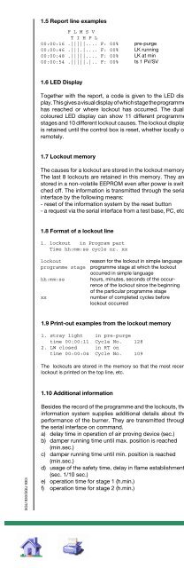
1.5 Report line examples<br />
F L M S V<br />
T I H P L<br />
00:00:16 .|||||.... F: 00%<br />
00:00:46 .|||.|.... F: 00%<br />
00:00:48 .|||||.... F: 00%<br />
00:00:54 .|||||.|.. F: 00%<br />
1.6 LED Display<br />
pre-purge<br />
LK running<br />
LK at min<br />
ts 1 PV/SV<br />
Together with the report, a code is given to the LED display.<br />
This gives a visual display of which stage the programme<br />
has reached or where lockout has occurred. The dualcoloured<br />
LED display can show 11 different programme<br />
stages and 10 different lockout causes. The lockout display<br />
is retained until the control box is reset, whether locally or<br />
remotely.<br />
1.7 Lockout memory<br />
The causes <strong>for</strong> a lockout are stored in the lockout memory.<br />
The last 8 lockouts are retained in this memory. They are<br />
stored in a non-volatile EEPROM even after power is switched<br />
off. The in<strong>for</strong>mation is transmitted through the serial<br />
interface by the following means:<br />
- reset of the in<strong>for</strong>mation system by the reset button<br />
- a request via the serial interface from a test base, PC, etc.<br />
1.8 Format of a lockout line<br />
1. lockout in Program part<br />
Time hh:mm:ss cycle nr. xx<br />
lockout<br />
programme stage<br />
hh:mm:ss<br />
xx<br />
reason <strong>for</strong> the lockout in simple language<br />
programme stage at which the lockout<br />
occurred in simple language<br />
hours, minutes, seconds of the occurrence<br />
of the lockout since the beginning<br />
of the particular programme stage<br />
number of completed cycles be<strong>for</strong>e<br />
lockout occurred<br />
1.9 Print-out examples from the lockout memory<br />
1. stray light in pre-purge<br />
time 00:00:11 Cycle No. 128<br />
2. LW closed in RT on<br />
time 00:00:04 Cycle No. 109<br />
The lockouts are stored in the memory so that the most recent<br />
lockout is printed on the top line, etc.<br />
1.10 Additional in<strong>for</strong>mation<br />
Besides the record of the programme and the lockouts, the<br />
in<strong>for</strong>mation system supplies additional details about the<br />
per<strong>for</strong>mance of the burner. They are transmitted through<br />
the serial interface on command.<br />
a) delay time in operation of air proving device (sec.)<br />
b) damper running time until max. position is reached<br />
(min.sec.)<br />
c) damper running time until min. position is reached<br />
(min.sec.)<br />
d) usage of the safety time, delay in flame establishment<br />
(sec. 1/10 sec.)<br />
e) operation time <strong>for</strong> stage 1 (h.min.)<br />
f) operation time <strong>for</strong> stage 2 (h.min.)<br />
3<br />
g) operation time of the control box (h.min.)<br />
h) number of programme cycles<br />
i) number of lockouts<br />
1.11 Print-out example<br />
SGU INFORMATION SYSTEM<br />
VERSION 1.0.4<br />
Auxiliary in<strong>for</strong>mation:<br />
LW switch time (sec): 20<br />
LK cycle time (min): 1.11<br />
LK cycle time (min): 0.18<br />
Ignition delay (sec): 1.60<br />
Hrs. low flame : 1.11<br />
Hrs. High flame : 1.31<br />
Hrs. control box : 3.30<br />
No. of cycles : 38<br />
No. of lockouts : 29<br />
Lockout in<strong>for</strong>mation:<br />
1. Flame out in Low flame<br />
Time 00:01:08 Cycle No. 38<br />
2. LW open in SI relay on<br />
Time 00:00:01 Cycle No. 37<br />
3. LK failure in LK running<br />
Time 00:00:29 Cycle No. 36<br />
4. LW open in SI relay on<br />
Time 00:00:15 Cycle No. 34<br />
5. No flame in End ts 1<br />
Time 00:00:01 Cycle No. 33<br />
6. LK failure in LK running<br />
Time 00:00:42 Cycle No. 32<br />
7. Flame out in Low flame<br />
Time 00:00:05 Cycle No. 31<br />
8. LW open in Pre-purge<br />
Time 00:00:02 Cycle No. 30<br />
00:00:00 ..|....... F: 00% Synch<br />
00:00:00 ..|....... F: 00% RT off<br />
F L M S V Flame Cycle<br />
h :m :s T I H P L signal step<br />
-------------------------------------<br />
00:00:09 .||.|..... F: 00% RT on<br />
00:00:02 .|..||.... F: 00% H relay on<br />
00:00:08 .|...|.... F: 00% LK running<br />
00:00:23 .||.||.... F: 00% LK at max.<br />
00:00:28 .|.|||.... F: 00% SI relay on<br />
00:00:29 .|||||.... F: 00% Pre-purge<br />
00:00:29 .|||.|.... F: 00% LK running<br />
00:01:01 .|||||.... F: 00% LK at min.<br />
00:01:23 .|||||.|.. F: 00% ts 1 PV/SV<br />
00:01:29 ||||||.|.. F: 00% End ts 1<br />
00:01:32 ||||||.||. F: 73% ts 2 V1<br />
00:01:38 ||||||..|. F: 78% End ts2<br />
00:01:40 ||||.|..|. F: 77% Low flame<br />
00:02:46 |.|||..... F: 77% Post-purge
