

SATRONIC - Control boxes for oil burners
SATRONIC - Control boxes for oil burners
SATRONIC - Control boxes for oil burners

You also want an ePaper? Increase the reach of your titles
YUMPU automatically turns print PDFs into web optimized ePapers that Google loves.
SGU 930/SGU 930i<br />
INIAN<br />
This command is used to check the self control function of<br />
the processor software and there<strong>for</strong>e whether the processor<br />
software itself works correctly. When the command<br />
"INIAN" is sent to the info system the following response<br />
must be reported:<br />
SGU INFORMATIONSSYSTEM<br />
VERSION 1.X.X<br />
If this report does not appear, then the processor itself is<br />
defective.<br />
2. Flame supervision<br />
Flame supervision can be carried out by one of the following<br />
detectors:<br />
- ionisation rod where the mains supply<br />
provides a neutral earth<br />
connection<br />
- U-V cell type UVZ 780 <strong>for</strong> <strong>oil</strong>/gas- and<br />
dual fuel <strong>burners</strong><br />
- Infra-red flicker detector type IRD 1020 <strong>for</strong> all type of<br />
<strong>burners</strong><br />
The different flame detectors are connected to separate<br />
terminals on the base, so that each detector is linked in the<br />
best possible way to the flame amplifier.<br />
The flame signal display at the front of the control box is a<br />
5-digit row of LED’s . It displays continuously the value of the<br />
flame current and provides a constant indication of the<br />
flame signal strength. Any change in flame signal strength<br />
can be recognised immediately and corrective action can<br />
be taken without delay.<br />
o.k.<br />
Flame signal display<br />
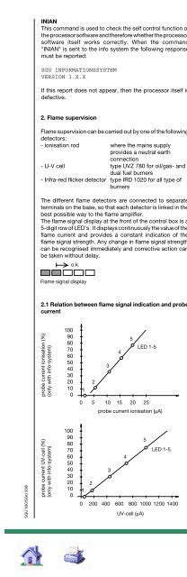
2.1 Relation between flame signal indication and probe<br />
current<br />
probe current ionisation (%)<br />
(only with info-system)<br />
probe current UV-cell (%)<br />
(only with info-system)<br />
100<br />
90<br />
80<br />
70<br />
60<br />
50<br />
40<br />
30<br />
20<br />
10<br />
0<br />
100<br />
90<br />
80<br />
70<br />
60<br />
50<br />
40<br />
30<br />
20<br />
10<br />
0<br />
1<br />
2<br />
3<br />
4<br />
0 5 10 15 20 25<br />
probe current ionisation (μA)<br />
1<br />
2<br />
3<br />
4<br />
0 200 400 600 800 1000 1200 1400<br />
5<br />
5<br />
UV-cell (μA)<br />
LED 1-5<br />
LED 1-5<br />
5<br />
3. <strong>Control</strong> sequence <strong>for</strong> the burner<br />
3.1 Selection of the programme<br />
The various control programmes can be selected by external<br />
selector switches or by the appropriate wiring to the base:<br />
- long pre-ignition time (terminal 18) or short pre-ignition<br />
time terminal 19<br />
- lockout or recycling due to loss of flame, recycling is<br />
selected by a link between terminal 34 + 35<br />
- ignition spark detection by U-V cell, no link between terminal<br />
36 + 37<br />
- fan motor with post-purge (terminal 17), or no post-purge<br />
terminal 16<br />
3.2 Conditions to start<br />
1. <strong>Control</strong> box at start position.<br />
Supply voltage connected to terminal 1 + N<br />
2. <strong>Control</strong>ling thermostat calls <strong>for</strong> heat and safety<br />
interlocks are closed (between terminals 2 + 3)<br />
3. Start command circuit SB, closed (terminals 7 + 8).<br />
These contacts may be open after approx. 6 secs.<br />
3.3 Air damper control<br />
With 3 separate output feeds, the air damper control can be<br />
set to either "closed", "low" air or "high" air positions. These<br />
monitored positions ensure "high" air <strong>for</strong> purging and "low"<br />
air be<strong>for</strong>e the initial release of fuel. Failure to reach both the<br />
"closed" and "high" air positions interrupt the control box<br />
sequence. If the air damper does not reach the required<br />
position within 100 seconds, the control box will go to lockout.<br />
Is no feed back from the air damper end position<br />
available, since no end contacts exist, then the terminals<br />
28 and 2 must be connected together. Note, the air damper<br />
position is no longer controlled with this change. The output<br />
terminals of the air damper control are electrically isolated<br />
from the internal circuit of the control box after power is<br />
switched to the high flame or modulation stage thermostat.<br />
The modulation stage thermostat LR then controls the air<br />
damper, depending on the required firing rates of V1 (main<br />
flame) or V2 (high flame).<br />
3.4 Air proving switch<br />
The changeover contact of the air proving switch is connected<br />
to the safety circuit of the control box. Practically, a<br />
changeover contact <strong>for</strong> a switching current of 0.5 A will be<br />
used. If the contact is not in the "no air" position, the control<br />
sequence will not start. If this check is satisfied, the burner<br />
motor and air damper motor circuits are switched on. Combustion<br />
air supply must be proved within 9 seconds or the<br />
control box will go to lockout. Supervision of the combustion<br />
air supply ends with the interruption of the control thermostat<br />
circuit, the post-purge period is not monitored. To operate<br />
burner with no air proving switch, the terminals 9, 10 and 11<br />
must be linked together.<br />
Note, at SGU 930i this change must be told to the infosystem<br />
(refer to 1.16 under LWBRE/LWBRA).<br />
3.5 Valves<br />
4 different valves can be connected, start valve or pilot<br />
valve, main valve (V1) and high flame or modulation stage<br />
valve (V2). On a single jet burner 3 firing rates can be<br />
achieved by use of the start valve and the main valves. Gas<br />
which flows through valves SV, V1 and V2 must join a<br />
common jet and the appropriate standards <strong>for</strong> the maximum<br />
firing rate of the start valve should be checked. Power is<br />
switched off to the pilot valve once the main flame is<br />
established. The maximum flow rate of the gas through the<br />
pilot valve is also limited by the relevant standard. It is not<br />
permitted to use the pilot valve and start valve at the same<br />
time.
