

SATRONIC - Control boxes for oil burners
SATRONIC - Control boxes for oil burners
SATRONIC - Control boxes for oil burners

You also want an ePaper? Increase the reach of your titles
YUMPU automatically turns print PDFs into web optimized ePapers that Google loves.
TECHNICAL FEATURES<br />
1. Oil and/or gas flames can be monitored.<br />
2. The flame detector and indicator control unit are suitable<br />
<strong>for</strong> operation where the ambient temperature lies within<br />
the range -20° to +60° C. (Please contact the manufacturer<br />
<strong>for</strong> in<strong>for</strong>mation on higher temperatures.)<br />
3. The working contact carries no potential difference,<br />
allowing the flame signal to be transmitted over large<br />
distances.<br />
4. The influence of possible stray light during the pre-purge<br />
phase or the intensity of the flame when the burner is<br />
operating is indicated by the row of 5 LED’s. The status<br />
of the relay is visible at any time.<br />
5. Sensitivity is adjustable.<br />
6. The compact dimensions of the detector allow it to be<br />
installed on any burner.<br />
7. The industrial version differs from the normal version by<br />
having a larger, robust, absolutely waterproof detector.<br />
8. Unlike UV tubes, the IRD 810/820 flicker detector does<br />
not deteriorate with age.<br />
INSTALLATION INSTRUCTIONS<br />
1. The detector probe should be fitted so that it receives the<br />
light which pulsates most strongly. This can be achieved<br />
by positioning the detector as close as possible to the<br />
flame or by directing it at a particular zone of the flame.<br />
2. No stray light must be allowed to fall on the detector (e.g.<br />
through cracks or from a sight glass). Pulsating stray<br />
light (e.g. from fluorescent lighting or light bulbs) could<br />
cause the system to switch to lockout.<br />
3. The infra-red flicker detector should be fitted in such a<br />
way that the ambient temperature cannot under any<br />
circumstances rise above 60° C. At higher temperatures,<br />
there is a risk of incorrect operation and the life expectancy<br />
of the unit could be reduced. In addition, care should be<br />
taken that the detector is not subjected to unusually<br />
harsh vibration and receives no hard knocks.<br />
4. The cable connecting the detector with the indicator<br />
control unit must not be disconnected. It must not,<br />
there<strong>for</strong>e, be shortened or lengthened.<br />
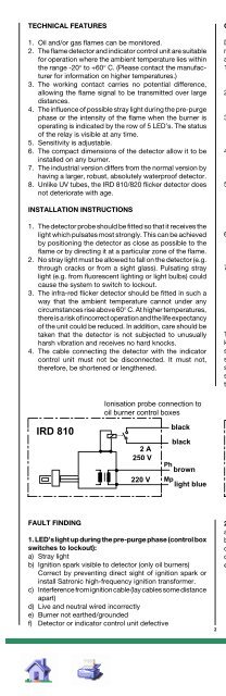
IRD 810<br />
FAULT FINDING<br />
Ionisation probe connection to<br />
<strong>oil</strong> burner control <strong>boxes</strong><br />
2 A<br />
250 V<br />
220 V<br />
black<br />
black<br />
Ph<br />
brown<br />
Mp<br />
light blue<br />
1. LED’s light up during the pre-purge phase (control box<br />
switches to lockout):<br />
a) Stray light<br />
b) Ignition spark visible to detector (only <strong>oil</strong> <strong>burners</strong>)<br />
Correct by preventing direct sight of ignition spark or<br />
install Satronic high-frequency ignition trans<strong>for</strong>mer.<br />
c) Interference from ignition cable (lay cables some distance<br />
apart)<br />
d) Live and neutral wired incorrectly<br />
e) Burner not earthed/grounded<br />
f) Detector or indicator control unit defective<br />
2<br />
COMMISSIONING AND MAINTENANCE<br />
During commissioning and after servicing, the flame<br />
monitoring system should be checked <strong>for</strong> faultless operation<br />
as follows:<br />
1. Check that the detector is connected properly. Wrong<br />
connections are a risk to safety, and could cause damage<br />
to the detector unit or burner system.<br />
2. Adjust to maximum sensitivity and start the burner. After<br />
the start impulse, no LED should light up during the prepurge<br />
phase.<br />
3. With the system set <strong>for</strong> normal operation, pull out the<br />
detector probe and cover it up to cut off light. The LED<br />
indicators must go out. The control box should switch to<br />
lockout or attempt to restart the sequence.<br />
4. Attempt to restart with the flame detector covered. There<br />
must be no indication from the LED’s. The burner control<br />
box must switch to lockout at the end of the safety<br />
interval.<br />
5. Attempt to start the burner with the detector exposed to<br />
stray light e.g. from fluorescent lighting, a cigarette<br />
lighter or light bulb (not daylight!). Depending on the type<br />
of control box, it should switch to lockout either<br />
immediately or at the end of the pre-purge, as a result of<br />
stray light.<br />
6. Re-insert the detector into its mount. When the burner is<br />
operating normally, carefully turn back the sensitivity<br />
control until only one LED is lit. The control box must<br />
switch to lockout or restart the sequence.<br />
7. Adjust the sensitivity to maximum. When the burner is<br />
operating normally, turn back the sensitivity control until<br />
only 4 LED’s light continuously.<br />
We recommend this method of adjustment, because in<br />
this way, changes in the burner settings, dirty detector<br />
probe etc. or also the influence of stray light, can be<br />
detected very easily. (The internal relay is activated when<br />
2 LED’s light.)<br />
The flame detection device requires no maintenance of any<br />
kind, and as it is classed as safety equipment, no attempt<br />
should be made to open the housing. The LED indicators<br />
should be checked visually at regular intervals. If a lower<br />
signal strength is indicated, it could mean that the burner<br />
settings have changed or that dirt and dust have reduced<br />
the amount of light reaching the detector.<br />
IRD 820<br />
Ionisation probe connection to<br />
<strong>oil</strong> and gas burner control <strong>boxes</strong><br />
black<br />
Ph<br />
brown<br />
Mp<br />
light blue<br />
2. No indication from LED’s after establishment of flame:<br />
a) Incorrect or faulty wiring<br />
b) Detector probe incorrectly installed („sees“ no light)<br />
c) Detector is dirty<br />
d) Sensitivity set at minimum<br />
e) Detector probe or indicator control unit defective<br />
IRD 810/820
