T-Series Climate Changer ® Air Handlers Sizes 3 through ... - Trane
T-Series Climate Changer ® Air Handlers Sizes 3 through ... - Trane
T-Series Climate Changer ® Air Handlers Sizes 3 through ... - Trane

You also want an ePaper? Increase the reach of your titles
YUMPU automatically turns print PDFs into web optimized ePapers that Google loves.
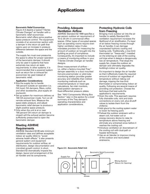
Barometric Relief Economizer<br />
Figure A-5 depicts a typical T-<strong>Series</strong><br />
<strong>Climate</strong> <strong>Changer</strong> <strong>®</strong> air handler with a<br />
barometric relief economizer.<br />
Barometric relief offers some positive<br />
space pressure control. The equipment<br />
consists of an economizer section with<br />
a damper in the return air path that<br />
opens upon an increase in pressure<br />
difference between the space and the<br />
outside.<br />
The supply fan must over-pressurize<br />
the space to allow for proper operation<br />
of the barometric damper. It should<br />
only be used in systems that have<br />
extremely low return air static<br />
requirements. In other systems, it is<br />
recommended that a powered system<br />
such as return fan or exhaust fan<br />
economizer be used instead of<br />
barometric relief.<br />
Application Considerations:<br />
• Size the supply fan to handle<br />
100 percent outside air operation (i.e.<br />
OA hood, OA dampers, filters, coil(s)<br />
and other accessories, plus supply air<br />
ductwork).<br />
• Set up system for maximum delivery at<br />
100 OA economizer mode. Turn on all<br />
remote exhaust fans. Measure the<br />
space static pressure, and adjust<br />
barometric relief damper to produce a<br />
slight positive space pressure.<br />
• Only when the unit is at or near<br />
100 percent OA (return air damper is<br />
closed) will the exhaust section become<br />
sufficiently pressurized to open the<br />
barometric damper.<br />
Meeting ASHRAE<br />
Requirements<br />
ASHRAE Standard 62-89 sets minimum<br />
ventilation rates and defines acceptable<br />
indoor air quality (IAQ) to “avoid<br />
adverse health effects.” It also presents<br />
general system and equipment<br />
requirements for outdoor airflow, air<br />
distribution, design documentation and<br />
microbial growth control. In short,<br />
Standard 62 dramatically impacts the<br />
design, layout and arrangement of the<br />
air handler and its components.<br />
Applications<br />
Providing Adequate<br />
Ventilation <strong>Air</strong>flow<br />
ASHRAE Standard 62-1989 specifies a<br />
per-person outdoor air requirement of<br />
15 to 20 cfm in commercial office<br />
spaces. (Other types of occupied spaces<br />
such as operating rooms require even<br />
higher ventilation rates.) It also<br />
mandates provision for measuring the<br />
amount of outdoor air brought into the<br />
building as proof of compliance.<br />
Consequently, it’s important to include<br />
a means of monitoring airflow in your<br />
T-<strong>Series</strong> <strong>Climate</strong> <strong>Changer</strong> air handler<br />
designs.<br />
Direct measurement of airflow –<br />
i.e., either a factory-mounted Traq damper assembly or a duct mounted<br />
hot-wire-anemometer or pitot-tube<br />
monitoring station provides greater<br />
accuracy and reliability than indirect<br />
monitoring methods such as<br />
mixed-temperature or tracer-gas<br />
calculations, fan-inlet monitors,<br />
fixed-position dampers or<br />
fixed-differential pressure plates.<br />
See “AHU Components: Mixing Box<br />
Section” later in this section for a brief<br />
summary of the Traq damper’s<br />
operating characteristics and<br />
application considerations.<br />
Figure A-5 - Barometric Relief Unit<br />
13<br />
Protecting Hydronic Coils<br />
from Freezing<br />
Bringing more outdoor air into the air<br />
handler to satisfy Standard 62’s<br />
ventilation requirement increases the<br />
likelihood of air stratification. If a layer<br />
of air below freezing moves <strong>through</strong><br />
the air handler, it can damage<br />
unprotected hydronic cooling and<br />
heating coils. Traditionally, a low-limit<br />
thermostat (or “freeze-stat”) installed<br />
on the entering-air side of the cooling<br />
coil trips when it detects a dangerously<br />
low air temperature. That stops the<br />
supply fan, closes the outdoor air<br />
damper and ultimately degrades the<br />
building’s indoor air quality.<br />
It’s important to design the air handler<br />
so that it effectively treats the required<br />
amount of outdoor air regardless of<br />
temperature without risking coil<br />
damage, tripping the low-limit<br />
thermostat or compromising indoor air<br />
quality. Following are several means of<br />
providing coil protection. Choose the<br />
technique that best suits the<br />
application’s requirements.<br />
• Drain the coils. This approach requires<br />
fully drainable coils, vent and drain<br />
connections on every coil, plus shutoff<br />
valves to isolate them from the<br />
chiller(s).<br />
• Add glycol to the cooling system water<br />
to lower its freezing point.<br />
• Preheat the outdoor airstream with a<br />
steam coil, hot-water coil or<br />
energy-recovery device to raise its<br />
temperature above freezing and<br />
eliminate any entrained snow before it<br />
reaches the cooling coil.<br />
• Introduce ventilation air downstream of<br />
the cooling coil with dual-path or<br />
bypass techniques.<br />
• Use an air blender to improve mixing<br />
of the outdoor and recirculated<br />
airstreams.