T-Series Climate Changer ® Air Handlers Sizes 3 through ... - Trane
T-Series Climate Changer ® Air Handlers Sizes 3 through ... - Trane
T-Series Climate Changer ® Air Handlers Sizes 3 through ... - Trane

You also want an ePaper? Increase the reach of your titles
YUMPU automatically turns print PDFs into web optimized ePapers that Google loves.
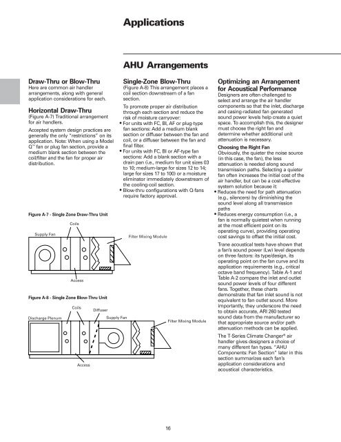
Draw-Thru or Blow-Thru<br />
Here are common air handler<br />
arrangements, along with general<br />
application considerations for each.<br />
Horizontal Draw-Thru<br />
(Figure A-7) Traditional arrangement<br />
for air handlers.<br />
Accepted system design practices are<br />
generally the only “restrictions” on its<br />
application. Note: When using a Model<br />
Q fan or plug fan section, provide a<br />
medium blank section between the<br />
coil/filter and the fan for proper air<br />
distribution.<br />
Figure A-7 - Single Zone Draw-Thru Unit<br />
Figure A-8 - Single Zone Blow-Thru Unit<br />
Applications<br />
AHU Arrangements<br />
Single-Zone Blow-Thru<br />
(Figure A-8) This arrangement places a<br />
coil section downstream of a fan<br />
section.<br />
To promote proper air distribution<br />
<strong>through</strong> each section and reduce the<br />
risk of moisture carryover:<br />
• For units with FC, BI, AF or plug-type<br />
fan sections: Add a medium blank<br />
section or diffuser between the fan and<br />
coil, or a diffuser between the fan and<br />
final filter.<br />
• For units with FC, BI or AF-type fan<br />
sections: Add a blank section with a<br />
drain pan (i.e., medium for unit sizes 03<br />
to 10; medium-large for sizes 12 to 14;<br />
large for sizes 17 to 100) or a moisture<br />
eliminator immediately downstream of<br />
the cooling-coil section.<br />
• Blow-thru configurations with Q-fans<br />
require factory approval.<br />
16<br />
Optimizing an Arrangement<br />
for Acoustical Performance<br />
Designers are often challenged to<br />
select and arrange the air handler<br />
components so that the inlet, discharge<br />
and casing-radiated fan generated<br />
sound power levels help create a quiet<br />
space. To accomplish this, the designer<br />
must choose the right fan and<br />
determine whether additional unit<br />
attenuation is necessary.<br />
Choosing the Right Fan<br />
Obviously, the quieter the noise source<br />
(in this case, the fan), the less<br />
attenuation is needed along sound<br />
transmission paths. Selecting a quieter<br />
fan often increases the initial cost of the<br />
air handler, but can be a cost-effective<br />
system solution because it:<br />
• Reduces the need for path attenuation<br />
(e.g., silencers) by diminishing the<br />
sound level along all transmission<br />
paths<br />
• Reduces energy consumption (i.e., a<br />
fan is normally quietest when running<br />
at the most efficient point on its<br />
operating curve), providing operating<br />
cost savings to offset the initial cost.<br />
<strong>Trane</strong> acoustical tests have shown that<br />
a fan’s sound power (Lw) level depends<br />
on three factors: its type/design, its<br />
operating point on the fan curve and its<br />
application requirements (e.g., critical<br />
octave band frequency). Table A-1 and<br />
Table A-2 compare the inlet and outlet<br />
sound power levels of four different<br />
fans. Together, these charts<br />
demonstrate that fan inlet sound is not<br />
equivalent to fan outlet sound. More<br />
importantly, they underscore the need<br />
to obtain accurate, ARI 260 tested<br />
sound data from the manufacturer so<br />
that appropriate source and/or path<br />
attenuation methods can be applied.<br />
The T-<strong>Series</strong> <strong>Climate</strong> <strong>Changer</strong> <strong>®</strong> air<br />
handler gives designers a choice of<br />
many different fan types. “AHU<br />
Components: Fan Section” later in this<br />
section summarizes each fan’s<br />
application considerations and<br />
acoustical characteristics.