T-Series Climate Changer ® Air Handlers Sizes 3 through ... - Trane
T-Series Climate Changer ® Air Handlers Sizes 3 through ... - Trane
T-Series Climate Changer ® Air Handlers Sizes 3 through ... - Trane

You also want an ePaper? Increase the reach of your titles
YUMPU automatically turns print PDFs into web optimized ePapers that Google loves.
Although they offer fewer options than<br />
5 /8-inch “shipping coils,” 1 /2-inch unit<br />
coils have a lower first cost and larger<br />
face area; they also require less<br />
distance (section length) reducing the<br />
air handler’s footprint.<br />
• 5 /8-inch shipping coils can be applied in<br />
either T-<strong>Series</strong> <strong>Climate</strong> <strong>Changer</strong> <strong>®</strong> air<br />
handlers or “built-up” air handling<br />
systems. Typified by 5 /8-inch OD tubes,<br />
these coils can be configure with 1 to<br />
12 rows, and 0.020, 0.024, 0.035 or<br />
0.049-inch tube walls.<br />
• Other coil options available include<br />
copper fins, stainless steel casings and<br />
1-inch OD steam coils. Compared to<br />
unit coils, shipping coils offer greater<br />
design versatility; however, they have a<br />
higher first cost, a smaller face area and<br />
require a longer section to promote<br />
proper air distribution.<br />
Application considerations for chilled<br />
water and direct expansion (DX) coils:<br />
• Size the coil to prevent moisture<br />
carryover due to high airflow velocities.<br />
Velocities up to 600 fpm a re acceptable<br />
depending on air conditions and coil fin<br />
arrangement.<br />
• Properly size the condensate trap to<br />
provide positive drainage; see<br />
Figure A-9.<br />
• Specify two-way-sloped drain pans to<br />
eliminate level seams and promote<br />
condensate flow directly to the drain<br />
outlet. Consider stainless steel<br />
construction to prolong drain pan life.<br />
• Provide adequate freeze protection for<br />
chilled water coils; see “AHU<br />
Functions: Comply with ASHRAE<br />
Standard 62-1989” earlier in this<br />
section.<br />
Application considerations for hot<br />
water coils:<br />
• Heating with hot water presents an<br />
attractive alternative for buildings<br />
without a ready source of steam<br />
• Providing effective freeze protection is<br />
more difficult for hot-water preheat<br />
coils than it is for steam. To minimize<br />
the risk of coil freeze-up, use<br />
face-and-bypass dampers and operate<br />
the coil at full capacity.<br />
Applications<br />
Application considerations for steam<br />
coils:<br />
• Properly pipe and trap the coil to<br />
provide positive drainage.<br />
• Steam coils are less susceptible to<br />
freeze-up than hot water coils. <strong>Trane</strong><br />
steam distribution coils use steam<br />
pressure to blow condensate from the<br />
coil. For additional freeze protection,<br />
use face-and-bypass dampers and<br />
operate the coil at full capacity.<br />
Face-and-Bypass Damper<br />
Section<br />
Designed to divert airflow around a<br />
coil, the face-and-bypass section can be<br />
used to control humidity or provide<br />
freeze protection for hydronic coils.<br />
Choose from the following damper<br />
section configurations:<br />
Internal Face-and-Bypass Dampers<br />
Typically used immediately upstream<br />
of a modified-size (i.e., less than<br />
100 percent airflow) coil, this option<br />
enables temperature control while<br />
operating the preheat coil at full flow.<br />
The dampers modulate to bypass air<br />
around the heating coil when the<br />
outdoor air temperature is warm<br />
enough to preclude freezing.<br />
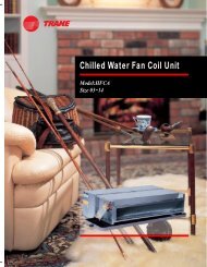
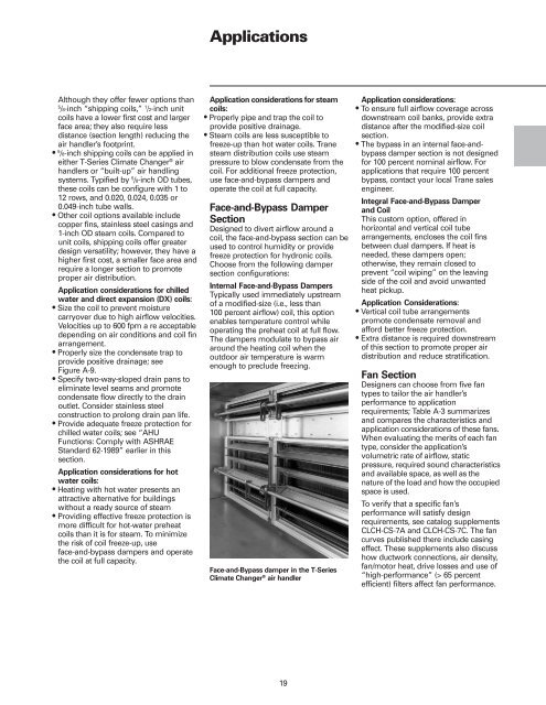
Face-and-Bypass damper in the T-<strong>Series</strong><br />
<strong>Climate</strong> <strong>Changer</strong> <strong>®</strong> air handler<br />
19<br />
Application considerations:<br />
• To ensure full airflow coverage across<br />
downstream coil banks, provide extra<br />
distance after the modified-size coil<br />
section.<br />
• The bypass in an internal face-andbypass<br />
damper section is not designed<br />
for 100 percent nominal airflow. For<br />
applications that require 100 percent<br />
bypass, contact your local <strong>Trane</strong> sales<br />
engineer.<br />
Integral Face-and-Bypass Damper<br />
and Coil<br />
This custom option, offered in<br />
horizontal and vertical coil tube<br />
arrangements, encloses the coil fins<br />
between dual dampers. If heat is<br />
needed, these dampers open;<br />
otherwise, they remain closed to<br />
prevent “coil wiping” on the leaving<br />
side of the coil and avoid unwanted<br />
heat pickup.<br />
Application Considerations:<br />
• Vertical coil tube arrangements<br />
promote condensate removal and<br />
afford better freeze protection.<br />
• Extra distance is required downstream<br />
of this section to promote proper air<br />
distribution and reduce stratification.<br />
Fan Section<br />
Designers can choose from five fan<br />
types to tailor the air handler’s<br />
performance to application<br />
requirements; Table A-3 summarizes<br />
and compares the characteristics and<br />
application considerations of these fans.<br />
When evaluating the merits of each fan<br />
type, consider the application’s<br />
volumetric rate of airflow, static<br />
pressure, required sound characteristics<br />
and available space, as well as the<br />
nature of the load and how the occupied<br />
space is used.<br />
To verify that a specific fan’s<br />
performance will satisfy design<br />
requirements, see catalog supplements<br />
CLCH-CS-7A and CLCH-CS-7C. The fan<br />
curves published there include casing<br />
effect. These supplements also discuss<br />
how ductwork connections, air density,<br />
fan/motor heat, drive losses and use of<br />
“high-performance” (> 65 percent<br />
efficient) filters affect fan performance.