ABS / AIR BAG 2004 USER GUIDE - OTC
ABS / AIR BAG 2004 USER GUIDE - OTC
ABS / AIR BAG 2004 USER GUIDE - OTC

You also want an ePaper? Increase the reach of your titles
YUMPU automatically turns print PDFs into web optimized ePapers that Google loves.
<strong>ABS</strong> / Air Bag <strong>2004</strong> User Guide Chapter 2: Start-up Steps<br />
Step 2: Connect the Cable<br />
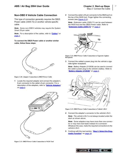
Non-OBD II Vehicle Cable Connection<br />
This type of connection generally requires the DB25<br />
Power cable (3305-72) or another vehicle-specific<br />
cable.<br />
Note: Some non-ODB II vehicles may require the System<br />
Smart 25-pin cable.<br />
Note: For a description of the cables, refer to “Cables” on<br />
page 3.<br />
To connect the DB25 Power cable or another similar<br />
cable, follow these steps:<br />
Figure 2.10: Adapter Connection to DB25 Power Cable<br />
1 Locate the required adapter and connect the adapter’s<br />
8-pin connector to the cable’s 8-pin connector. For a<br />
description of the adapters, refer to “Vehicle Adapters”<br />
on page 4.<br />
Figure 2.11: DB25 Power Cable Connection to NGIS Tool<br />
2 Connect the cable’s 25-pin connector to the DB25 port on<br />
the top of the NGIS tool. Finger tighten the connecting<br />
screws (see Figure 2.11).<br />
Note: Extension cable (3305-71) can be used between<br />
the NGIS tool and the DB25 Power cable. Refer to<br />
“Extension Cable (3305-71)” on page 3.<br />
Figure 2.12: DB25 Power Cable Connection to Cigarette Lighter<br />
Receptacle<br />
3 Connect the cables’s power plug into the vehicle’s cigarette<br />
lighter receptacle.<br />
Note: Battery Adapter (212638) can be used to connect<br />
the cable’s power plug to the vehicle’s battery. Refer to<br />
“Battery Adapter (212638)” on page 5.<br />
Figure 2.13: DB25 Power Cable Connection to Vehicle’s DLC<br />
4 Connect the adapter’s connector to the vehicle’s DLC.<br />
Note: The vehicle’s DLC is not always located under the<br />
dash as shown above.<br />
Note: Some adapters may have more than one connector<br />
or may have test leads instead of a connector.<br />
Whatever the case, make the required connections to the<br />
vehicle’s DLC.<br />
5 Continue with the next section, “Step 3: Select the Diagnostic<br />
Function” on page 18.<br />
17