ABS READER II USER GUIDE - OTC
ABS READER II USER GUIDE - OTC
ABS READER II USER GUIDE - OTC

You also want an ePaper? Increase the reach of your titles
YUMPU automatically turns print PDFs into web optimized ePapers that Google loves.
16<br />
<strong>ABS</strong> Reader <strong>II</strong> User Guide<br />
Step 2: Connect the Cable<br />
To connect the System Smart 25-pin cable, follow these<br />
steps:<br />
1 Locate the required cable and any SSI or cable adapter<br />
as required. If necessary, do one of the following:<br />
• For the System Smart 25-pin cable, insert the SSI into<br />
the port on the top of the cable’s 25-pin connector.<br />
• For the DB25 Power cable, connect the adapter’s 8pin<br />
connector to the cable’s<br />
8-pin connector.<br />
• The OBD <strong>II</strong> Smart Cable does not require an additional<br />
SSI or adapter cable.<br />
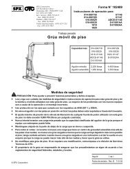
Figure 2.8: SSI Connection and System Smart 25-pin Cable (left),<br />
Adapter Connection to DB25 Power Cable (right) and OBD <strong>II</strong> Smart<br />
Cable (bottom).<br />
2 Connect the 25-pin connector to the DB25 port on the top<br />
of the <strong>ABS</strong> Reader <strong>II</strong> tool. Finger tighten the connecting<br />
screws.<br />
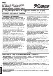
Figure 2.9: Typical Cable Connection to <strong>ABS</strong> Reader <strong>II</strong> Tool<br />
IMPORTANT: Make sure you have correctly<br />
entered the vehicle information in the scan<br />
tool; incorrect vehicle identification can produce<br />
unexpected test results.<br />
Note: Leave the Required Cables screen displayed on the<br />
scan tool. Do not turn the scan tool off.<br />
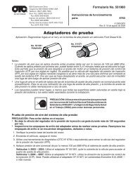
Figure 2.10: Cable Connection to Vehicle DLC: OBD <strong>II</strong> Smart Cable<br />
or System Smart 25-pin cable (shown on left) and DB25 Power Cable<br />
3 Connect the cables’s J-1962 (16 pin) connector into the<br />
vehicle’s J-1962 DLC (16 pin), located under the vehicle<br />
dash.<br />
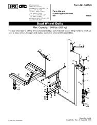
4 If required, connect the cable’s power plug into the vehicle’s<br />
cigarette lighter receptacle.<br />
5 Connect the cable to the vehicle’s DLC.<br />
Note: The vehicle’s DLC is not always located under the<br />
dash as shown above.<br />
Note: Some adapters may have more than one connector<br />
or may have test leads instead of a connector.<br />
Whatever the case, make the required connections to the<br />
vehicle’s DLC.<br />
6 With the Required Cables illustration still displayed on the<br />
scan tool, press the ENTER key. This initiates communication<br />
with the vehicle’s computer and displays the next<br />
screen.<br />
Note: If the communication indicator on the scan tool is<br />
not lit, check the cable and power connections.