ABS READER II USER GUIDE - OTC
ABS READER II USER GUIDE - OTC
ABS READER II USER GUIDE - OTC

Create successful ePaper yourself
Turn your PDF publications into a flip-book with our unique Google optimized e-Paper software.
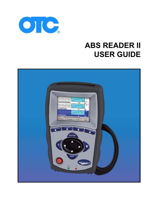
<strong>ABS</strong> <strong>READER</strong> <strong>II</strong><br />
<strong>USER</strong> <strong>GUIDE</strong>
IMPORTANT NOTICES<br />
SAFETY<br />
For your safety, follow all Danger, Warning and Important notes. These safety messages are<br />
in the following formats:<br />
DANGER:<br />
Means you risk possible loss of life.<br />
WARNING:<br />
Means you risk possible bodily harm.<br />
IMPORTANT: Means that the information demands special attention<br />
or that you risk damage to the vehicle or the tool.<br />
Note: Added to provide clarity and helpful tips.<br />
These safety messages cover situations SPX is aware of. SPX cannot know, evaluate and advise you as<br />
to all of the possible hazards. You must be certain that any conditions or service procedures encountered<br />
do not jeopardize your personal safety.<br />
COPYRIGHT<br />
No part of this manual may be reproduced, stored in a retrieval system or transmitted, in any form or by any<br />
means, electronic, mechanical, photocopying, recording, or otherwise, without the prior written permission<br />
of SPX.<br />
DISCLAIMER<br />
All information, illustrations, and specifications contained in this technical instruction manual are based on the latest<br />
information available at the time of publication. The right is reserved to make changes at any time without obligation<br />
to notify any person or organization of such revisions or changes. Further, SPX shall not be liable for errors contained<br />
herein or for incidental or consequential damages (including lost profits) in connection with the furnishing,<br />
performance or use of this material.<br />
© 2008 SPX Corporation. All rights reserved.
Contents<br />
IMPORTANT NOTICES . . . . . . . . . . . . . . . . . . . . . . . . . . . . . . . . . . . . . . . . . . . . . . . . 2<br />
SAFETY . . . . . . . . . . . . . . . . . . . . . . . . . . . . . . . . . . . . . . . . . . . . . . . . . . . . . . . . . . . . 2<br />
Chapter 1: General Information . . . . . . . . . . . . . . . . . . . . . . . . . . . . . . .1<br />
Introduction . . . . . . . . . . . . . . . . . . . . . . . . . . . . . . . . . . . . . . . . . . . . . . . . . . . . . . . . 1<br />
Application Features . . . . . . . . . . . . . . . . . . . . . . . . . . . . . . . . . . . . . . . . . . . . . . . . . 1<br />
<strong>ABS</strong> Reader <strong>II</strong> Tool Features . . . . . . . . . . . . . . . . . . . . . . . . . . . . . . . . . . . . . . . . . . . 2<br />
Cables. . . . . . . . . . . . . . . . . . . . . . . . . . . . . . . . . . . . . . . . . . . . . . . . . . . . . . . . . . . . . .3<br />
ScanMate PC Software. . . . . . . . . . . . . . . . . . . . . . . . . . . . . . . . . . . . . . . . . . . . . . . . 4<br />
Launch the ScanMate application. . . . . . . . . . . . . . . . . . . . . . . . . . . . . . . . . . . . . . . . . 4<br />
Install the PC Software . . . . . . . . . . . . . . . . . . . . . . . . . . . . . . . . . . . . . . . . . . . . . . . . . 5<br />
Scan Tool Printing Procedure . . . . . . . . . . . . . . . . . . . . . . . . . . . . . . . . . . . . . . . . . . . . 5<br />
Software Screens . . . . . . . . . . . . . . . . . . . . . . . . . . . . . . . . . . . . . . . . . . . . . . . . . . . . . 6<br />
Datastream . . . . . . . . . . . . . . . . . . . . . . . . . . . . . . . . . . . . . . . . . . . . . . . . . . . . . . . . . . 7<br />
Custom Datastream . . . . . . . . . . . . . . . . . . . . . . . . . . . . . . . . . . . . . . . . . . . . . . . . . . . 7<br />
TPMS Quick Reference Information . . . . . . . . . . . . . . . . . . . . . . . . . . . . . . . . . . . . . . . 8<br />
Vehicle Applications . . . . . . . . . . . . . . . . . . . . . . . . . . . . . . . . . . . . . . . . . . . . . . . . 10<br />
Chapter 2: Start-up Steps . . . . . . . . . . . . . . . . . . . . . . . . . . . . . . . . . . . .11<br />
Introduction . . . . . . . . . . . . . . . . . . . . . . . . . . . . . . . . . . . . . . . . . . . . . . . . . . . . . . . 11<br />
<strong>ABS</strong> Reader <strong>II</strong> Power . . . . . . . . . . . . . . . . . . . . . . . . . . . . . . . . . . . . . . . . . . . . . . . . 11<br />
Adjust Default Settings . . . . . . . . . . . . . . . . . . . . . . . . . . . . . . . . . . . . . . . . . . . . . . 12<br />
Test Startup and Vehicle Connection . . . . . . . . . . . . . . . . . . . . . . . . . . . . . . . . . . . 12<br />
Step 1: Enter the Vehicle Information. . . . . . . . . . . . . . . . . . . . . . . . . . . . . . . . . . . 13<br />
Step 2: Connect the Cable . . . . . . . . . . . . . . . . . . . . . . . . . . . . . . . . . . . . . . . . . . . . 15<br />
Step 3: Select the Diagnostic Function . . . . . . . . . . . . . . . . . . . . . . . . . . . . . . . . . 17<br />
Chapter 3: Quick DTC Scan (Supported Systems) . . . . . . . . . . . . . . .19<br />
Basic Test Procedure . . . . . . . . . . . . . . . . . . . . . . . . . . . . . . . . . . . . . . . . . . . . . . . . 19<br />
DTC Related Repair Information . . . . . . . . . . . . . . . . . . . . . . . . . . . . . . . . . . . . . . . 20<br />
Chapter 4: Datastream . . . . . . . . . . . . . . . . . . . . . . . . . . . . . . . . . . . . . .21<br />
About Datastream. . . . . . . . . . . . . . . . . . . . . . . . . . . . . . . . . . . . . . . . . . . . . . . . . . . 21<br />
Automatic Diagnostic Code Triggered Record . . . . . . . . . . . . . . . . . . . . . . . . . . . 21<br />
Basic Datastream Procedure. . . . . . . . . . . . . . . . . . . . . . . . . . . . . . . . . . . . . . . . . . 21<br />
Datastream Functions . . . . . . . . . . . . . . . . . . . . . . . . . . . . . . . . . . . . . . . . . . . . . . . 22<br />
Record and Playback . . . . . . . . . . . . . . . . . . . . . . . . . . . . . . . . . . . . . . . . . . . . . . . . . 23<br />
Graph/Digital. . . . . . . . . . . . . . . . . . . . . . . . . . . . . . . . . . . . . . . . . . . . . . . . . . . . . . . . 24<br />
Lock . . . . . . . . . . . . . . . . . . . . . . . . . . . . . . . . . . . . . . . . . . . . . . . . . . . . . . . . . . . . . .25<br />
To Top . . . . . . . . . . . . . . . . . . . . . . . . . . . . . . . . . . . . . . . . . . . . . . . . . . . . . . . . . . . . . 25<br />
Freeze Frame . . . . . . . . . . . . . . . . . . . . . . . . . . . . . . . . . . . . . . . . . . . . . . . . . . . . . . . 26<br />
Pathfinder . . . . . . . . . . . . . . . . . . . . . . . . . . . . . . . . . . . . . . . . . . . . . . . . . . . . . . . . . . 26<br />
Print . . . . . . . . . . . . . . . . . . . . . . . . . . . . . . . . . . . . . . . . . . . . . . . . . . . . . . . . . . . . . .27<br />
Zoom. . . . . . . . . . . . . . . . . . . . . . . . . . . . . . . . . . . . . . . . . . . . . . . . . . . . . . . . . . . . . . 27<br />
Sort . . . . . . . . . . . . . . . . . . . . . . . . . . . . . . . . . . . . . . . . . . . . . . . . . . . . . . . . . . . . . . .28<br />
English/Metric Units . . . . . . . . . . . . . . . . . . . . . . . . . . . . . . . . . . . . . . . . . . . . . . . . . . 29<br />
Chapter 5: Custom Datastream . . . . . . . . . . . . . . . . . . . . . . . . . . . . . . .31<br />
Chapter 6: Diagnostic Trouble Codes . . . . . . . . . . . . . . . . . . . . . . . . . .33<br />
Read Codes. . . . . . . . . . . . . . . . . . . . . . . . . . . . . . . . . . . . . . . . . . . . . . . . . . . . . . . . 34<br />
Read and Display Codes . . . . . . . . . . . . . . . . . . . . . . . . . . . . . . . . . . . . . . . . . . . . . . 34<br />
Read Codes Only . . . . . . . . . . . . . . . . . . . . . . . . . . . . . . . . . . . . . . . . . . . . . . . . . . . . 35<br />
Review Codes . . . . . . . . . . . . . . . . . . . . . . . . . . . . . . . . . . . . . . . . . . . . . . . . . . . . . . 37<br />
Clear Codes . . . . . . . . . . . . . . . . . . . . . . . . . . . . . . . . . . . . . . . . . . . . . . . . . . . . . . . 38<br />
Self-Diagnostics . . . . . . . . . . . . . . . . . . . . . . . . . . . . . . . . . . . . . . . . . . . . . . . . . . . . 39<br />
Wiggle Test . . . . . . . . . . . . . . . . . . . . . . . . . . . . . . . . . . . . . . . . . . . . . . . . . . . . . . . . 41<br />
Read Codes / Clear Codes (Flash Codes) . . . . . . . . . . . . . . . . . . . . . . . . . . . . . . . 42<br />
Read Codes (Flash Codes) . . . . . . . . . . . . . . . . . . . . . . . . . . . . . . . . . . . . . . . . . . . . 42<br />
Clear Codes (Flash Codes) . . . . . . . . . . . . . . . . . . . . . . . . . . . . . . . . . . . . . . . . . . . . 43<br />
Chapter 7: Post Collision Test. . . . . . . . . . . . . . . . . . . . . . . . . . . . . . . . .45<br />
<strong>ABS</strong> Reader <strong>II</strong> User Guide<br />
Contents<br />
-i
0<br />
<strong>ABS</strong> Reader <strong>II</strong> User Guide<br />
Contents<br />
Chapter 8: Pathfinder Troubleshooting . . . . . . . . . . . . . . . . . . . . . . . . 47<br />
Repair Trac . . . . . . . . . . . . . . . . . . . . . . . . . . . . . . . . . . . . . . . . . . . . . . . . . . . . . . 48<br />
TSB References . . . . . . . . . . . . . . . . . . . . . . . . . . . . . . . . . . . . . . . . . . . . . . . . . . . . 49<br />
Specifications . . . . . . . . . . . . . . . . . . . . . . . . . . . . . . . . . . . . . . . . . . . . . . . . . . . . . . 50<br />
Component Location . . . . . . . . . . . . . . . . . . . . . . . . . . . . . . . . . . . . . . . . . . . . . . . . 50<br />
Brake Bleed Procedure . . . . . . . . . . . . . . . . . . . . . . . . . . . . . . . . . . . . . . . . . . . . . . 52<br />
Brake Bleed Sequence. . . . . . . . . . . . . . . . . . . . . . . . . . . . . . . . . . . . . . . . . . . . . . . 53<br />
Chapter 9: Vehicle Info . . . . . . . . . . . . . . . . . . . . . . . . . . . . . . . . . . . . . 55<br />
Specifications . . . . . . . . . . . . . . . . . . . . . . . . . . . . . . . . . . . . . . . . . . . . . . . . . . . . . . 55<br />
Related TSBs . . . . . . . . . . . . . . . . . . . . . . . . . . . . . . . . . . . . . . . . . . . . . . . . . . . . . . 56<br />
System Type . . . . . . . . . . . . . . . . . . . . . . . . . . . . . . . . . . . . . . . . . . . . . . . . . . . . . . . 57<br />
PROM Identification . . . . . . . . . . . . . . . . . . . . . . . . . . . . . . . . . . . . . . . . . . . . . . . . . 57<br />
Chapter 10: TPMS Quick Reference . . . . . . . . . . . . . . . . . . . . . . . . . . 59<br />
Chapter 11: Special Tests. . . . . . . . . . . . . . . . . . . . . . . . . . . . . . . . . . . . 61<br />
Basic Special Test Procedure . . . . . . . . . . . . . . . . . . . . . . . . . . . . . . . . . . . . . . . . . 61<br />
Special Test Descriptions . . . . . . . . . . . . . . . . . . . . . . . . . . . . . . . . . . . . . . . . . . . . 62<br />
<strong>ABS</strong> Manual Control Tests. . . . . . . . . . . . . . . . . . . . . . . . . . . . . . . . . . . . . . . . . . . . . .62<br />
<strong>ABS</strong> Motor Test . . . . . . . . . . . . . . . . . . . . . . . . . . . . . . . . . . . . . . . . . . . . . . . . . . . . . .62<br />
<strong>ABS</strong> Version Test. . . . . . . . . . . . . . . . . . . . . . . . . . . . . . . . . . . . . . . . . . . . . . . . . . . . .62<br />
Actuator Tests . . . . . . . . . . . . . . . . . . . . . . . . . . . . . . . . . . . . . . . . . . . . . . . . . . . . . . .62<br />
Autobleed Test, Automated Bleed, or Service Bleed. . . . . . . . . . . . . . . . . . . . . . . . . .62<br />
Automated Test . . . . . . . . . . . . . . . . . . . . . . . . . . . . . . . . . . . . . . . . . . . . . . . . . . . . . .63<br />
Brake Bleed Preparation Test . . . . . . . . . . . . . . . . . . . . . . . . . . . . . . . . . . . . . . . . . . .63<br />
Function Test . . . . . . . . . . . . . . . . . . . . . . . . . . . . . . . . . . . . . . . . . . . . . . . . . . . . . . . .63<br />
Gear Tension Relief Test . . . . . . . . . . . . . . . . . . . . . . . . . . . . . . . . . . . . . . . . . . . . . . .63<br />
Hydraulic Control Tests . . . . . . . . . . . . . . . . . . . . . . . . . . . . . . . . . . . . . . . . . . . . . . . .63<br />
Idle Up Manual Control Test . . . . . . . . . . . . . . . . . . . . . . . . . . . . . . . . . . . . . . . . . . . .63<br />
Lamp Tests . . . . . . . . . . . . . . . . . . . . . . . . . . . . . . . . . . . . . . . . . . . . . . . . . . . . . . . . .63<br />
Manual Control Test . . . . . . . . . . . . . . . . . . . . . . . . . . . . . . . . . . . . . . . . . . . . . . . . . .63<br />
Motor Rehome Test . . . . . . . . . . . . . . . . . . . . . . . . . . . . . . . . . . . . . . . . . . . . . . . . . . .63<br />
Pump Motor Tests . . . . . . . . . . . . . . . . . . . . . . . . . . . . . . . . . . . . . . . . . . . . . . . . . . . .64<br />
Relay Test . . . . . . . . . . . . . . . . . . . . . . . . . . . . . . . . . . . . . . . . . . . . . . . . . . . . . . . . . .64<br />
Requested Torque Test . . . . . . . . . . . . . . . . . . . . . . . . . . . . . . . . . . . . . . . . . . . . . . . .64<br />
Setup SDM Serial Number (Air Bag Sensing and Diagnostic Module) . . . . . . . . . . . .64<br />
Solenoid Tests . . . . . . . . . . . . . . . . . . . . . . . . . . . . . . . . . . . . . . . . . . . . . . . . . . . . . . .64<br />
System Identification . . . . . . . . . . . . . . . . . . . . . . . . . . . . . . . . . . . . . . . . . . . . . . . . . .64<br />
TCS Test . . . . . . . . . . . . . . . . . . . . . . . . . . . . . . . . . . . . . . . . . . . . . . . . . . . . . . . . . . .64<br />
Traction Control System (TCS) Manual Control Tests. . . . . . . . . . . . . . . . . . . . . . . . .64<br />
Voltage Load Test . . . . . . . . . . . . . . . . . . . . . . . . . . . . . . . . . . . . . . . . . . . . . . . . . . . .64<br />
Special Test Screen Examples . . . . . . . . . . . . . . . . . . . . . . . . . . . . . . . . . . . . . . . . 65<br />
Instructional Screen Example . . . . . . . . . . . . . . . . . . . . . . . . . . . . . . . . . . . . . . . . . . .65<br />
Chapter 12: Global OBD <strong>II</strong> . . . . . . . . . . . . . . . . . . . . . . . . . . . . . . . . . . 69<br />
View the Quick Test Results . . . . . . . . . . . . . . . . . . . . . . . . . . . . . . . . . . . . . . . . . . 69<br />
Diagnostic OBD <strong>II</strong> Trouble Codes . . . . . . . . . . . . . . . . . . . . . . . . . . . . . . . . . . . . . . 70<br />
Read Codes/Pending Codes. . . . . . . . . . . . . . . . . . . . . . . . . . . . . . . . . . . . . . . . . . . .70<br />
Clear Codes . . . . . . . . . . . . . . . . . . . . . . . . . . . . . . . . . . . . . . . . . . . . . . . . . . . . . . . .71<br />
Freeze Frame . . . . . . . . . . . . . . . . . . . . . . . . . . . . . . . . . . . . . . . . . . . . . . . . . . . . . . .71<br />
Special Tests (OBD <strong>II</strong>). . . . . . . . . . . . . . . . . . . . . . . . . . . . . . . . . . . . . . . . . . . . . . . . 72<br />
Basic Proceedure . . . . . . . . . . . . . . . . . . . . . . . . . . . . . . . . . . . . . . . . . . . . . . . . . . . .72<br />
Non-Continuous Tests . . . . . . . . . . . . . . . . . . . . . . . . . . . . . . . . . . . . . . . . . . . . . . . . .73<br />
Oxygen Sensor Tests . . . . . . . . . . . . . . . . . . . . . . . . . . . . . . . . . . . . . . . . . . . . . . . . .73<br />
Readiness Test . . . . . . . . . . . . . . . . . . . . . . . . . . . . . . . . . . . . . . . . . . . . . . . . . . . . . .75<br />
Vehicle Identification . . . . . . . . . . . . . . . . . . . . . . . . . . . . . . . . . . . . . . . . . . . . . . . . . .75<br />
Device Control. . . . . . . . . . . . . . . . . . . . . . . . . . . . . . . . . . . . . . . . . . . . . . . . . . . . . . .76<br />
SPX Corporation Limited Warranty . . . . . . . . . . . . . inside back cover<br />
Technical Service . . . . . . . . . . . . . . . . . . . . . . . . . . . . . . . . . . . . . . . .inside back cover
Safety Precautions<br />
Danger:<br />
<strong>ABS</strong> Reader <strong>II</strong> User Guide<br />
Safety Precautions<br />
• When an engine is operating, keep the service area WELL VENTILATED or attach a building<br />
exhaust removal system to the engine exhaust system. Engines produce carbon monoxide,<br />
an odorless, poisonous gas that causes slower reaction time and can lead to serious injury<br />
or death.<br />
Warning:<br />
• When working with hydraulic or fuel lines, liquids under pressure may escape and create a<br />
dangerous condition. Never open a bleeder valve or loosen a hydraulic line while the <strong>ABS</strong><br />
is pressurized. Use adequate ventilation and make sure there are no sparks or possibility of<br />
sparks present that may ignite any vapor.<br />
• Wear an American National Standards Institute (ANSI) approved eye shield when testing or<br />
repairing vehicles. Objects propelled by whirling engine components or pressurized liquids<br />
escaping may cause personal injury.<br />
• Set the parking brake and block the wheels before testing or repairing a vehicle. It is especially<br />
important to block the wheels on front-wheel drive vehicles because the parking brake does<br />
not hold the drive wheels.<br />
• Do not drive the vehicle and operate the <strong>ABS</strong> Reader <strong>II</strong> tool at the same time. Any distractions may<br />
cause an accident. Have one person operate the <strong>ABS</strong> Reader <strong>II</strong> tool as another person drives the<br />
vehicle.<br />
• Maintain adequate clearance around moving components or belts during testing. Moving<br />
components and belts can catch loose clothing, body parts, or test equipment and cause<br />
serious damage or personal injury.<br />
• Automotive batteries contain sulfuric acid and produce explosive gases that can result in<br />
serious injury. To prevent ignition of gases, keep lighted cigarettes, sparks, flames, and other<br />
ignition sources away from the battery at all times. If you are using the battery as a power<br />
source, connect the RED (+) battery clip to the positive vehicle battery terminal and connect<br />
the BLACK (-) battery clip to a good ground away from the battery.<br />
• Refer to the service manual for the vehicle being serviced and adhere to all diagnostic<br />
procedures and precautions. Failure to do so could result in air bag deployment, personal<br />
injury, or otherwise unneeded air bag system repairs.<br />
• Only use specially designed replacement parts (brake hoses and lines) for <strong>ABS</strong>-equipped<br />
vehicles.<br />
• After bleeding the brake system, check the brake pedal for excessive travel or a “spongy”<br />
feel. Bleed again if either condition is present.<br />
• When installing transmitting devices (Citizen Band radio, telephone, etc.) on <strong>ABS</strong>-equipped<br />
vehicles, do not locate the antenna near the <strong>ABS</strong> control unit or any other control unit.<br />
i
ii<br />
<strong>ABS</strong> Reader <strong>II</strong> User Guide<br />
Safety Precautions<br />
Important:<br />
• To avoid damaging the <strong>ABS</strong> Reader <strong>II</strong> tool or generating false data, make sure the vehicle battery is fully<br />
charged and the connection to the vehicle DLC is clean and secure.<br />
• Never disconnect or reconnect any electrical connector while the ignition is on. Damage to the <strong>ABS</strong><br />
control unit may result.<br />
• Do not hammer speed rings into the hub or tap on speed sensor components (sensor, sensor rings, etc.).<br />
Speed rings must be pressed, not hammered, into the hub and striking or tapping speed sensor<br />
components can cause demagnetization or a loss of polarization, affecting the accuracy of the<br />
speed signal returning to the <strong>ABS</strong> control unit.<br />
• Use the recommended anti-corrosion coating on speed sensor components: Do not contaminate<br />
with grease.<br />
• When speed sensor components have been removed, be sure to check the sensor-to-ring gap,<br />
when applicable.<br />
• Do not mix tire sizes. Increasing the width slightly is acceptable but rolling diameter must be identical<br />
for all tires. Some manufacturers recommend tires of the same brand, style, and type. Failure to<br />
follow this precaution may cause inaccurate wheel speed readings.<br />
• Do not expose the <strong>ABS</strong> control unit to prolonged periods of high heat: 185 degrees F/85 degrees C<br />
for 2 hours is considered a maximum limit.<br />
• Use a recommended brake fluid, do not use silicone brake fluids in an <strong>ABS</strong>-equipped vehicle.<br />
• Before bleeding the brake system, make sure no diagnostic codes are present.<br />
• Do not let the master cylinder run dry during the brake bleeding procedure.<br />
• Do not allow brake fluid to contact the motor pack or the electrical connectors.<br />
VW Note:<br />
• For model years 2000 and 2001 VW Golf, GTI, Jetta/Bora, and Beetle air bag controllers there are reports of<br />
air bag warning lights staying on permanently after scanning with a scan tool. The air bag controller shows<br />
DTC number 65535, indicating an internal error which cannot be cleared. This problem seems to be limited<br />
to air bag controllers with the part number 6Q0-909-605-A. There are a number of different index or colorcode<br />
variations of this controller and not all of them are affected. If you have a 2000 or 2001 Golf, Jetta/Bora,<br />
Beetle, or a similar SEAT or Skoda model, physically inspect the air bag controller and look at the part<br />
number. If it is not 6Q0-909-605-A, then it should be safe to test. If it is Q0-909-605-A, then it is at risk of this<br />
problem — avoid testing the air bag controller.
<strong>ABS</strong> Reader <strong>II</strong> User Guide Chapter 1: General Information<br />
Introduction<br />
1: General Information<br />
Introduction<br />
The <strong>ABS</strong> Reader <strong>II</strong> automotive scan tool applications<br />
read Diagnostic Trouble Codes (DTCs), view “live” data<br />
readings from a vehicle’s Electronic Control Units<br />
(ECUs), and save recordings of the data. The following<br />
applications are available for on-vehicle diagnostic<br />
testing:<br />
USA 2008 <strong>ABS</strong>/Airbag Application — This<br />
application reads the vehicle’s Anti-lock Brake System<br />
(<strong>ABS</strong>) codes and sensor data, provides air bag<br />
information and performs device control tests.<br />
Tire Pressure Monitor Systems Application — This<br />
application reads the vehicle’s Tire Pressure<br />
Monitoring System (TPMS) codes and sensor data.<br />
Application Features<br />
• A Datastream functions views “live” sensor and<br />
switch datastream information while the data is being<br />
communicated from the vehicle’s ECU.<br />
• A Diagnostic Trouble Code (DTC) scan function and<br />
a Quick DTC Scan reads the DTCs for Tire Pressure<br />
Monitoring Systems (TPMS), Air Bags and<br />
Anti-lock Brake Systems (<strong>ABS</strong>). In addition, you can<br />
manually enter diagnostic codes for vehicles without<br />
readable ECUs.<br />
• Record (Save) and Playback functions let you record<br />
and replay datastream DTC information similar to a<br />
video recorder function.<br />
• An automatic DTC triggered record function automatically<br />
creates a recording for playback and alerts you<br />
whenever a DTC occurs during testing.<br />
• A Post Collision test provides instructions for testing<br />
air bags after repair(s).<br />
• Pathfinder Troubleshooting and Vehicle Info functions<br />
let you view vehicle-specific information, such as technical<br />
service bulletin (TSB) references, vehicle<br />
specifications, repair instructions, ECU component<br />
location(s), and brake bleed procedures.<br />
• Special Tests include programmed diagnostic procedures<br />
(special tests) for bi-directional control tests on<br />
anti-lock brake systems.<br />
TPMS Quick Reference Information — This<br />
application provides TPMS system description, reset<br />
procedure, reset trigger and torque specifications. For<br />
details, see “Chapter 10: TPMS Quick Reference” on<br />
page 59<br />
Global OBD <strong>II</strong> Application — This application<br />
provides diagnostic testing of On Board Diagnostics <strong>II</strong><br />
(OBD <strong>II</strong>) compliant USA domestic, Asian, and<br />
European vehicles. For details, see “Chapter 12:<br />
Global OBD <strong>II</strong>” on page 69<br />
Playback — for viewing saved recordings.<br />
System Setup — for adjusting default settings for the<br />
scan tool. For details, see “Adjust Default Settings”<br />
on page 12.<br />
1
2<br />
<strong>ABS</strong> Reader <strong>II</strong> User Guide<br />
<strong>ABS</strong> Reader <strong>II</strong> Tool Features<br />
<strong>ABS</strong> Reader <strong>II</strong> Tool Features<br />
9<br />
10 1<br />
7<br />
8<br />
Figure 1.1: <strong>ABS</strong> Reader <strong>II</strong> Front View<br />
Item 1 LCD Screen — displays the menus and data<br />
screens.<br />
Item 2 ENTER Key — executes a selected menu option<br />
and/or displays the next screen.<br />
Item 3 LIGHT Key — turns the LCD backlight on when using<br />
internal battery power. When using external power,<br />
the backlight stays on when the tool is on.<br />
Item 4 EXIT Key — exits a screen. Cancels a selected<br />
menu option.<br />
Item 5 Communication Indicator — indicates when the<br />
scan tool is properly connected and communicating<br />
with the vehicle’s ECU.<br />
Item 6 External Power Indicator — indicates when the<br />
scan tool is drawing power from a source other than<br />
the internal batteries, such as from an OBD <strong>II</strong> vehicle<br />
cable connection, the cigarette lighter power<br />
adapter, or an accessory AC / DC power adapter.<br />
Item 7 On/Off Button — turns the scan tool on and off.<br />
When using external power, the scan tool stays on<br />
until you turn it off. When using internal battery<br />
power, the scan tool turns off automatically after a set<br />
time.<br />
Item 8 HELP Key — displays helpful information.<br />
Item 9 Arrow Keys (Up, Down, Left, and Right) — select<br />
a menu option or scroll through a screen of data or<br />
text.<br />
Item 10 Variable Function Keys — four keys that<br />
correspond with “buttons” on some screens; execute<br />
special commands.<br />
5<br />
6<br />
2<br />
4<br />
3<br />
Figure 1.2: <strong>ABS</strong> Reader <strong>II</strong> Back View<br />
Item 1 Battery Compartment and Cover — holds six (6)<br />
1.5 volt batteries.<br />
Item 2 Flash Card Port — holds the flash card (for scan tool<br />
updates).<br />
2<br />
Figure 1.3: <strong>ABS</strong> Reader <strong>II</strong> Top View<br />
Item 1 DB25 Connection — (25-Pin) connects to the<br />
vehicle Data Link Connector (DLC) cable.<br />
Item 2 External Power Port — connects the power<br />
adapter.<br />
Item 3 Universal Serial Bus (USB) Port or RS232 Port —<br />
connects host devices such as a Personal Computer.<br />
1<br />
1<br />
2<br />
3<br />
3
<strong>ABS</strong> Reader <strong>II</strong> User Guide Chapter 1: General Information<br />
<strong>ABS</strong> Reader <strong>II</strong> Tool Features<br />
Cables<br />
The cable used to connect the <strong>ABS</strong> Reader <strong>II</strong> tool to the Data<br />
Link Connector (DLC) of a vehicle’s electronic control unit<br />
(ECU) depends on the type of vehicle being tested. The two<br />
most common cables are shown below. They are the System<br />
Smart 25-pin cable (3305-73) and the DB25 power cable<br />
(3305-72). An optional extension cable may also be used.<br />
Note: The <strong>ABS</strong> Reader <strong>II</strong> software tells you which cable must<br />
be used for the vehicle you are testing. For details, refer to<br />
“Step 1: Enter the Vehicle Information” on page 13.<br />
System Smart 25-Pin Cable (3305-73)<br />
1<br />
2<br />
3<br />
Figure 1.4: System Smart 25-Pin Cable<br />
The System Smart 25-pin cable is for OBD ll vehicles.<br />
The cable has the following components:<br />
Item 1 J-1962 Connector - connects to the vehicle DLC.<br />
Item 2 System Smart Insert (SSI) - inserts into the port on<br />
the top of the 25-pin connector. The SSI needed is<br />
specified during vehicle information entry.<br />
Item 3 25-pin Male Connector - connects to the DB25 port<br />
located on the top of the <strong>ABS</strong> Reader <strong>II</strong> tool.<br />
DB25 Power Cable (3305-72)<br />
Figure 1.5: DB25 Power Cable<br />
The DB25 power cable is for non-OBD ll vehicles and<br />
some OBD <strong>II</strong> vehicles. The cable has the following<br />
components:<br />
Item 1 8-Pin Adapter Connector - connects to the adapter<br />
cable for the vehicle being tested. T<br />
Item 2 Power Plug - inserts into the vehicle’s cigarette<br />
lighter receptacle.<br />
Item 3 25-pin Male Connector - connects to the DB25 port<br />
located on the top of the <strong>ABS</strong> Reader <strong>II</strong> tool.<br />
OBD <strong>II</strong> Smart Cable (3421-88)<br />
Figure 1.6: OBD <strong>II</strong> Smart Cable<br />
1 2 3<br />
1 2<br />
Item 1 25-pin Male Connector - connects to the DB25 port<br />
located on the top of the <strong>ABS</strong> Reader <strong>II</strong> tool.<br />
Item 2 J-1962 Connector - connects to the vehicle DLC.<br />
3
4<br />
<strong>ABS</strong> Reader <strong>II</strong> User Guide<br />
ScanMate PC Software<br />
ScanMate PC Software<br />
The ScanMate software application lets you view and print live data and upload playback data files to a personal<br />
computer (PC) from a connected scan tool.<br />
Scan Tool/PC Connection<br />
To use the ScanMate application for printing data directly from the scan tool or for uploading playback event files<br />
from the scan tool, connect the USB cable to the scan tool USB port and your PC USB port. If your <strong>ABS</strong> Reader<br />
does not have the USB port, connect the RS232 cable to the scan tool RS232 port and to your PC serial port.<br />
Launch the ScanMate application<br />
To start the ScanMate application, click the Windows desktop icon or select ScanMate from the Windows Start<br />
menu. The first window that appears is the ScanMate main window. This window has function buttons at the top<br />
for accessing the software functions. They include the following:<br />
Figure 1.7: ScanMate Main Window<br />
Event Upload — checks for a scan tool connection, looks for saved<br />
playback files on the scan tool, uploads the playback files to the PC, and<br />
then displays a dialog box for you to open a playback file for viewing.<br />
Note: To upload playback files, disconnect the scan tool from the vehicle.<br />
Playback — displays a dialog box for you to select a playback file to open.<br />
After you select a file, it opens in a separate Playback window. You can<br />
review, save, or delete the playback file.<br />
Note: To view playback files on the PC, you must first upload the files with<br />
the Event Upload function. Then, to playback and print the uploaded files,<br />
the scan tool and PC do not have to be connected.<br />
Scan Tool Print — displays a dialog box for you to print data directly from<br />
the scan tool. This can be live data you are viewing or it can be playback<br />
data saved in the scan tool. (See the procedure on page 9.)<br />
Tool Update — for future use for updating the scan tool.<br />
Utility — displays a window for you to enter shop information, change the<br />
software language, and view software information.<br />
Help — displays the ScanMate Help System window.<br />
Exit — closes the application.<br />
For step-by-step instructions, start the ScanMate application and click the Help<br />
button.
<strong>ABS</strong> Reader <strong>II</strong> User Guide Chapter 1: General Information<br />
ScanMate PC Software<br />
Install the PC Software<br />
The ScanMate CD installs the software and User Guide<br />
on your personal computer (PC).<br />
PC Requirements<br />
The PC should have the following minimum<br />
requirements:<br />
• Microprocessor: 233 MHz Pentium, minimum<br />
• RAM: 128 MB, minimum (256 MB recommended)<br />
• Hard Disk (C drive): 60 MB free space, minimum<br />
• PC Communication Port: 9-pin serial COM port<br />
• Display (Monitor): Color, set at 800 × 600 pixel,<br />
minimum<br />
• Operating System: Microsoft ® Windows<br />
XP ® (updated with current service packs) and<br />
Microsoft Vista. ®<br />
• Internet Browser: Microsoft Internet Explorer 5.0 or<br />
newer<br />
Software Installation<br />
Use the following steps to install the software.<br />
1 Insert the ScanMate CD in your PCs CD drive and follow<br />
the on-screen instructions. Be aware of the following:<br />
• The install software uses Windows auto-play<br />
technology. This means the installation<br />
instructions appear on your PC screen<br />
automatically.<br />
If the instructions do not appear automatically,<br />
click the Windows Start button and click Run. This<br />
displays a Run dialog box. Click the Browse<br />
button and then find and select your CD drive.<br />
After this, select the Setup.exe file and click the<br />
Open button (or OK). Then click the OK button in<br />
the Run box.<br />
• The installation places a ScanMate icon on the<br />
Windows desktop and places the ScanMate<br />
option on the Windows Start, Programs menu.<br />
You can use either one of these to start the<br />
software application. Refer to Scanmate<br />
Software, on page 6.<br />
2 When the installation is finished, remove the CD from the<br />
PCs CD drive<br />
New Scan Tool Application Updates<br />
To obtain new application updates, contact your local<br />
distributor.<br />
Scan Tool Printing Procedure<br />
To print data directly from the scan tool, the scan tool<br />
must be connected to a PC that has the ScanMate<br />
software installed and prepared for printing. Use the<br />
following steps as a reference for printing. For detailed<br />
instructions use the ScanMate application’s Help<br />
System.<br />
1 Make sure the scan tool is connected to the PC. For<br />
details, refer to Scan Tool/PC Connection, on page 6.<br />
2 Start the ScanMate application on the PC.<br />
3 On the ScanMate main window, click the Print<br />
button. This displays the ScanMate Print dialog box.<br />
Figure 1.8: ScanMate Print Dialog Box<br />
4 In the ScanMate Print dialog box, do the following:<br />
a Select the COM port for the scan tool<br />
connection and click the CONNECT button.<br />
b Check the display area. If it contains data<br />
you do not want to print, click the Clear<br />
button.<br />
5 On the scan tool, display the data to print and press the<br />
Print key. This uploads the data to the display area in the<br />
ScanMate Print dialog box on the PC.<br />
6 In the ScanMate Print dialog box, view the data and click<br />
the Print button to print the data to the PCs default printer.<br />
Note: The scan tool header prints on all reports. For details,<br />
refer to “Adjust Default Settings” on page 12<br />
5
6<br />
<strong>ABS</strong> Reader <strong>II</strong> User Guide<br />
ScanMate PC Software<br />
Software Screens<br />
This section contains an overview of the main screens<br />
in the <strong>ABS</strong> Reader <strong>II</strong> software. Some of the screens<br />
contain menus and others contain test instructions or<br />
results.<br />
Application Manager Screen<br />
When you turn on the <strong>ABS</strong> Reader <strong>II</strong> tool, the Application<br />
Manager screen appears. The Application<br />
Manager screen contains a menu of the groups of software<br />
installed in the <strong>ABS</strong> Reader <strong>II</strong> tool.<br />
Figure 1.9: Application Manager Screen<br />
From the Application Manager screen, select from the<br />
Programs available and then press the ENTER key. This<br />
displays the first Vehicle Identification screen.<br />
Vehicle Identification Screen<br />
Figure 1.10: Vehicle Identification Screen<br />
The Vehicle Identification screen has the following<br />
sections:<br />
• top section - displays the cable connections required for<br />
the vehicle.<br />
• bottom section - contains the function keys for:<br />
• entering new information for a vehicle,<br />
• selecting and reusing information for a vehicle previously<br />
tested,<br />
• viewing demonstration data.<br />
For detailed information about using this screen, refer<br />
to “Step 1: Enter the Vehicle Information” on page 13<br />
Vehicle Identification - Required Cables<br />
Screen<br />
Figure 1.11: Vehicle Identification - Required Cables Screen<br />
After you have entered all the information for a vehicle,<br />
the top section displays the vehicle information and the<br />
middle section displays the cable connections required<br />
for the vehicle.<br />
For detailed information about using this screen, refer<br />
to “Cables” on page 3 and “Step 2: Connect the<br />
Cable” on page 15.
<strong>ABS</strong> Reader <strong>II</strong> User Guide Chapter 1: General Information<br />
ScanMate PC Software<br />
Diagnostic Menu Screen<br />
Figure 1.12: Diagnostic Menu Screen<br />
The Diagnostic Menu screen contains a menu of the<br />
test options available for the vehicle being tested. The<br />
next few pages show and briefly describe each of the<br />
options on the Diagnostic menu.<br />
Note: The screen shown above is an example screen. It<br />
shows all possible options that can appear on the Diagnostic<br />
menu. Only the options available for the vehicle being tested<br />
will appear on this menu.<br />
Datastream<br />
When you select Datastream from the Diagnostic<br />
menu, the following screen appears.<br />
Figure 1.13: Datastream Screen<br />
This screen displays live data from the vehicle’s electronic<br />
control unit (ECU) in digital or graphical format;<br />
English or Metric units. From this screen, you can also<br />
record, print, and sort the data.For detailed information<br />
about using this screen, refer to “Chapter 4:<br />
Datastream” on page 21.<br />
Custom Datastream<br />
When you select Custom Datastream from the Diagnostic<br />
menu, the following screen appears.<br />
Figure 1.14: Custom Datastream Selection Screen - before selections<br />
Use this screen to select specific (customized) data<br />
items you want to display on the standard<br />
Datastream screen.<br />
Figure 1.15: Custom Datastream Selection Screen - after selections<br />
For detailed information about using the Custom<br />
Datastream menu option, refer to “Chapter 5: Custom<br />
Datastream” on page 31.<br />
7
8<br />
<strong>ABS</strong> Reader <strong>II</strong> User Guide<br />
ScanMate PC Software<br />
Diagnostic Trouble Codes<br />
The Diagnostic Trouble Code (DTC) options that<br />
appear on the Diagnostic Menu screen vary depending<br />
on the vehicle being tested. For some vehicles, the<br />
menu option is Diagnostic Trouble Codes; for other<br />
vehicles, there are two menu options: Read Codes and<br />
Clear Codes.<br />
The Diagnostic Trouble Codes option appears on the<br />
Diagnostic Menu screen for vehicles that allow reading<br />
of DTCs with a scan tool.<br />
The Read Codes and Clear Codes options appear on<br />
the Diagnostic Menu screen (instead of the Diagnostic<br />
Codes option) for vehicles that require reading of DTCs<br />
by visually viewing them as flash codes. For this type<br />
of vehicle, you identify the vehicle’s flash code numbers<br />
and manually enter the numbers into the <strong>ABS</strong> Reader<br />
<strong>II</strong> tool to see their descriptions.<br />
When you use the DTC options, a screen similar to the<br />
following screen appears. The screen displays diagnostic<br />
test code DTC numbers and descriptions.<br />
Figure 1.16: DTC Information Screen<br />
For detailed information about using the DTC options,<br />
refer to “Chapter 6: Diagnostic Trouble Codes” on<br />
page 33.<br />
Post Collision Test<br />
When you select Post Collision Test from the Diagnostic<br />
menu several step-by-step instruction screens,<br />
similar to the following screen, appear.<br />
Figure 1.17: Post Collision Test Screen<br />
The screens provide instructions for testing air bags<br />
after repair(s). For detailed information about using the<br />
screens, refer to “Chapter 7: Post Collision Test” on<br />
page 45.<br />
TPMS Quick Reference Information<br />
When you select TPMS Quick Reference Information<br />
ffrom the Diagnostic menu, the following screen<br />
appears.<br />
Figure 1.18: TPMS Quick Reference Information<br />
The TPMS Reference screen contains menu options<br />
for viewing vehicle-specific information.<br />
For detailed information about using the screens, refer<br />
to “Chapter 10: TPMS Quick Reference” on page 59.
<strong>ABS</strong> Reader <strong>II</strong> User Guide Chapter 1: General Information<br />
ScanMate PC Software<br />
Pathfinder Troubleshooting<br />
When you select Pathfinder Troubleshooting from<br />
the Diagnostic menu, the following screen appears.<br />
Figure 1.19: Pathfinder Screen<br />
The Pathfinder screen contains menu options for viewing<br />
vehicle-specific information such as Repair Trac,<br />
brake bleed procedures and more.<br />
For detailed information, refer to “Chapter 8: Pathfinder<br />
Troubleshooting” on page 47.Vehicle Info<br />
When you select Vehicle Info from the Diagnostic<br />
menu, the following screen appears.<br />
Figure 1.20: Vehicle Info Screen<br />
The Vehicle Info screen contains menu options for<br />
viewing vehicle-specific information such as vehicle<br />
specifications and more.<br />
For detailed information, refer to “Chapter 9: Vehicle<br />
Info” on page 55.<br />
Controller ID<br />
When you select Controller ID from the Diagnostic<br />
menu, the following screen appears.<br />
Figure 1.21: ECU Identification Data Screen<br />
The ECU Identification screen contains information<br />
about the selected ECU.<br />
9
10<br />
<strong>ABS</strong> Reader <strong>II</strong> User Guide<br />
Vehicle Applications<br />
Special Tests<br />
When you select Special Tests from the Diagnostic<br />
menu, the following screen appears.<br />
Figure 1.22: Special Tests Screen<br />
The Special Tests screen contains menu options for<br />
performing special diagnostic tests. After you select a<br />
menu option, pre-programmed screens appear for the<br />
diagnostic test.<br />
Note: The screen shown above is only an example. It shows<br />
only a few of the possible options that can appear on the<br />
screen.<br />
For detailed information, refer to “Chapter 11: Special<br />
Tests” on page 61.<br />
Vehicle Applications<br />
The <strong>ABS</strong> Reader <strong>II</strong> Vehicle Applications Reference<br />
Guide is available as a portable document format (pdf)<br />
file. The Reference Guide contains a listing of the vehicles<br />
and ECUs that the <strong>ABS</strong> Reader <strong>II</strong> software works<br />
with.<br />
To open the Reference Guide, double-click the <strong>ABS</strong><br />
Reader <strong>II</strong> User Guide icon on the Windows desktop.<br />
This displays a Select User Guide window.<br />
Note: To view the Guide, the Adobe Acrobat Reader software<br />
application must be installed on the PC. When you open<br />
the Guide, if an Open With box appears, click the Cancel button<br />
and do one of the following to install Acrobat Reader:<br />
To install an English version, insert the <strong>ABS</strong> Reader <strong>II</strong> CD into<br />
the PCs CD drive. When the installation Welcome window<br />
appears, click Cancel, then Yes, then Finish. Then click the<br />
Windows Start button and click Run to display the Run box.<br />
Click the Browse button and then select My Computer, The<br />
CD drive, and AcroReader51_ENU.exe. Click the Open button<br />
(or OK). Then click the OK button in the Run box and<br />
follow the on-screen instructions.<br />
To install a version for another language, go to the website:<br />
http://www.adobe.com/products/acrobat/<br />
reader_archive.html#Win<br />
Disclaimer: Acrobat Reader is licensed and copyrighted<br />
by Adobe Systems Incorporated. It is provided<br />
as a courtesy, not a license for use. If you install it, you<br />
must accept and abide by the terms of its license agreement,<br />
which display the first time you start the<br />
application.
<strong>ABS</strong> Reader <strong>II</strong> User Guide Chapter 2: Start-up Steps<br />
Introduction<br />
2: Start-up Steps<br />
Introduction<br />
<strong>ABS</strong> Reader <strong>II</strong> Power<br />
Setup includes providing power to the scan tool, adjusting<br />
default settings, and installing the ScanMate PC<br />
software.<br />
Figure 2.1: Batteries and Power Cord<br />
Before using the scan tool, provide power from either<br />
six (6) internal 1.5 volt batteries or from an external<br />
power adapter. OBD <strong>II</strong> vehicle cable connections also<br />
provide external power through the vehicle DLC to the<br />
scan tool.<br />
• The 1.5 volt batteries can be either alkaline or rechargeable<br />
nickel metal hydride (NiMH) batteries. Insert the<br />
batteries into the battery compartment on the back side<br />
of the scan tool.<br />
IMPORTANT: Use only high-quality batteries. During<br />
long periods of storage, remove the batteries to<br />
prevent damage from battery leakage.<br />
• The cigarette lighter power adapter provides power from<br />
the vehicle’s battery. For some scan tool functions (System<br />
Setup, Playback), use of the adapter is optional but<br />
preserves the life of the internal batteries. For other functions<br />
(OBD I testing), use of the adapter is required. To<br />
use the adapter, insert the pin into the port on the top of<br />
the scan tool and insert the plug into the vehicle’s cigarette<br />
lighter. Turn the vehicle’s ignition key to the On (Run)<br />
position.<br />
• Accessory components are available for connecting the<br />
scan tool directly to the vehicle’s battery or to an electrical<br />
outlet. For details, refer to the User Guide.<br />
IMPORTANT: To conserve internal battery life, use<br />
either an OBD <strong>II</strong> vehicle cable connection or a power<br />
adapter as the scan tool’s primary power source: do<br />
not use the internal batteries as the primary power<br />
source. Use the internal batteries only when adjusting<br />
default scan tool settings, during test startup (for<br />
vehicle identification), or when uploading files to the<br />
ScanMate software on a PC. To conserve battery<br />
power, use the backlight in poorly-lit conditions<br />
only.<br />
11
12<br />
<strong>ABS</strong> Reader <strong>II</strong> User Guide<br />
Adjust Default Settings<br />
Adjust Default Settings<br />
The System Setup functions let you view information<br />
about the scan tool and adjust default settings as<br />
follows:<br />
1 Press the On / Off button to turn the scan tool on, wait for<br />
the Application Manager screen to appear.<br />
Figure 2.2: Application Manager Screen and System Setup Screen<br />
2 Use the Down Arrow key to select System Setup and<br />
then press the ENTER key. This displays the System<br />
Setup screen, shown in Figure 2.2.<br />
3 Use the Down Arrow key to select an item to adjust<br />
(described below) and then press the ENTER key.<br />
• Contrast Adjust — adjust the contrast of the<br />
LCD screen.<br />
• Print Header — set up a heading for reports that you<br />
print from the scan tool.<br />
• Unit Defaults — set the date, time, units-ofmeasure,<br />
and automatic shut down time. It also<br />
lets you turn the audible beep and print header<br />
functions on or off.<br />
• Revision Levels — display software version<br />
numbers.<br />
• Technical Support — display technical support<br />
information.<br />
• Hardware Tests — test the LCD screen, keypad<br />
keys, and beeper and view the time clock and<br />
serial number for the scan tool.<br />
• Language — set the default language for the<br />
scan tool software.<br />
• External Memory Card Check — check the<br />
system files on a compact flash card in the<br />
compact flash port.<br />
4 Follow any on-screen instructions; use the Arrow keys as<br />
needed to adjust settings; use the EXIT key to exit the<br />
screens. For detailed instructions, refer to the User Guide.<br />
Test Startup and Vehicle<br />
Connection<br />
All vehicle setups require a specific cable connection<br />
to the vehicle DLC. To determine the specific cable<br />
required for a vehicle, you must first enter the vehicle<br />
information. After you have done this, the screen displays<br />
the specific cable information for the vehicle. You<br />
then use this information to connect the correct cable<br />
to the DLC and proceed with the vehicle diagnostics.<br />
This chapter includes the following general steps to get<br />
you started:<br />
1 Enter the vehicle information to determine the correct<br />
cable required.<br />
2 Connect the required cable.<br />
3 Select the diagnostic function you want to perform.<br />
WARNING: Before performing any diagnostic<br />
functions, refer to the Safety Precautions, instructions,<br />
and the warnings provided by the vehicle<br />
manufacturer. In addition, follow any warnings and<br />
descriptions provided on the scan tool screens.
<strong>ABS</strong> Reader <strong>II</strong> User Guide Chapter 2: Start-up Steps<br />
Step 1: Enter the Vehicle Information<br />
Step 1: Enter the Vehicle<br />
Information<br />
Use the following steps to enter vehicle information<br />
and to determine which cable to use for communication<br />
connection between the <strong>ABS</strong> Reader <strong>II</strong> tool and the<br />
vehicle DLC.<br />
To enter the vehicle information, follow these steps:<br />
Note: Before doing these steps, make sure the battery for<br />
the <strong>ABS</strong> Reader <strong>II</strong> tool is charged.<br />
1 Press the power button on the <strong>ABS</strong> Reader <strong>II</strong> tool to turn<br />
the tool on. This displays the Application Manager screen.<br />
Figure 2.3: Application Manager Screen<br />
2 Select an application, such as USA 2008 <strong>ABS</strong>/Airbag,<br />
and press the ENTER key. This displays the first Vehicle<br />
Information screen.<br />
Figure 2.4: Vehicle Information - Manufacturer Screen<br />
3 With the Vehicle Information screen displayed, you can<br />
enter new information for a vehicle or you can select and<br />
reuse saved information for a vehicle already tested. Do<br />
one of the following:<br />
• To enter new information for a vehicle, go to step 4<br />
and then step 6.<br />
• To reuse saved information for a vehicle already<br />
tested go to step 5 and then step 6.<br />
IMPORTANT: For model years 2000 and 2001<br />
VW Golf, GTI, Jetta/Bora, and Beetle air bag<br />
controllers there are reports of air bag warning<br />
lights staying on permanently after scanning<br />
with a scan tool. The air bag controller shows<br />
DTC number 65535, indicating an internal error<br />
which cannot be cleared. This problem seems<br />
to be limited to air bag controllers with the part<br />
number 6Q0-909-605-A. There are a number of<br />
different index or color-code variations of this<br />
controller and not all of them are affected. If<br />
you have a 2000 or 2001 Golf, Jetta/Bora, Beetle,<br />
or a similar SEAT or Skoda model, physically<br />
inspect the air bag controller and look at<br />
the part number. If it is not 6Q0-909-605-A, then<br />
it should be safe to test. If it is Q0-909-605-A,<br />
then it is at risk of this problem — avoid testing<br />
the air bag controller.<br />
13
14<br />
<strong>ABS</strong> Reader <strong>II</strong> User Guide<br />
Step 1: Enter the Vehicle Information<br />
4 To enter new information for a vehicle, do the following:<br />
a Select the vehicle manufacturer and press the<br />
ENTER key. This displays the selected vehicle<br />
description in the top part of the screen and changes<br />
the middle part of the screen to the next screen of a<br />
series of screens.<br />
Note: The screens shown are examples. The screens<br />
that actually appear are different for each vehicle.<br />
Figure 2.5: Vehicle Information - Series of Screens<br />
b On each screen that appears, select the correct<br />
option and then press the ENTER key. Do this until<br />
the complete vehicle information is entered and the<br />
illustration of the required cables appears, as shown<br />
in Figure 2.7.<br />
Note: On the Vehicle Information screens, you can press the<br />
Demo function key to display demonstration data in the software.<br />
The Demo function stays on until you press the function<br />
key again to turn it off. When the Demo function is on, a checkmark<br />
appears in the box on the function key.<br />
5 To reuse saved information for a vehicle already tested,<br />
do the following:<br />
a Press the Reuse function key. This displays the<br />
Reuse Vehicles screen, which contains a list of saved<br />
vehicle descriptions.<br />
Figure 2.6: Reuse Vehicles Screen<br />
b Select the vehicle description to use and press the<br />
ENTER key. This displays the illustration of the<br />
required cables, as shown in Figure 2.7.<br />
Note: The Reuse Vehicles list holds 25 vehicle descriptions.<br />
When the list is full, old descriptions automatically delete as<br />
you enter new descriptions. To prevent a description from<br />
being automatically deleted, highlight the description and<br />
press the Save function key. This places a disk icon to the<br />
left of the file name and saves the description until you delete<br />
it. (Use the Delete function key to delete a selected<br />
description.)
<strong>ABS</strong> Reader <strong>II</strong> User Guide Chapter 2: Start-up Steps<br />
Step 2: Connect the Cable<br />
6 After you have entered new vehicle information or<br />
selected a vehicle description to reuse, the Required<br />
Cables illustration displays on the Vehicle Identification<br />
screen. With this screen displayed, make the required<br />
cable connections.<br />
Note: Some vehicles do not have an ECU and do not require<br />
a cable connection. For these vehicles, the screen states that<br />
no cable connection is required. If this happens, go to “Step<br />
3: Select the Diagnostic Function” on page 17.<br />
Figure 2.7: Vehicle Information - Required Cables Screen<br />
Note: For some vehicles, this screen illustrates the vehicle’s<br />
DLC test terminals rather than the required cables. If this happens,<br />
go to “Read Codes / Clear Codes (Flash Codes)” on<br />
page 42<br />
To display demonstration data in the software, press<br />
the function key that corresponds to the Demo button.<br />
A checkmark in the box indicates the Demo function is<br />
on (press the key again to turn the function off).<br />
Step 2: Connect the Cable<br />
The method used to connect the <strong>ABS</strong> Reader <strong>II</strong> tool to<br />
a vehicle’s ECU depends on the vehicle’s configuration<br />
as follows:<br />
• OBD <strong>II</strong> - A vehicle equipped with an On Board Diagnostics<br />
Two (OBD <strong>II</strong>) vehicle management system uses the OBD<br />
<strong>II</strong> Smart cable (3421-88). If the OBD <strong>II</strong> cable is not available,<br />
use a System Smart 25-pin cable (3305-73). This<br />
cable is used along with a System Smart Insert (SSI).<br />
Both the OBD <strong>II</strong> Smart cable and the System Smart 25pin<br />
cable supply communication and 12-volt power<br />
through a standardized J-1962 data link connection<br />
(DLC).<br />
• Non-OBD <strong>II</strong> - A vehicle not equipped with an OBD <strong>II</strong> system<br />
generally uses the DB25 Power cable (3305-72),<br />
which supplies communication through a DLC connection<br />
and supplies 12-volt power through the cigarette lighter<br />
receptacle or a connection to the battery. This cable is<br />
used along with a vehicle cable adapter. (Some non-ODB<br />
<strong>II</strong> vehicles may require the System Smart 25-pin cable.)<br />
Note: Connections described above charge the scan tool’s<br />
battery while connected.<br />
15
16<br />
<strong>ABS</strong> Reader <strong>II</strong> User Guide<br />
Step 2: Connect the Cable<br />
To connect the System Smart 25-pin cable, follow these<br />
steps:<br />
1 Locate the required cable and any SSI or cable adapter<br />
as required. If necessary, do one of the following:<br />
• For the System Smart 25-pin cable, insert the SSI into<br />
the port on the top of the cable’s 25-pin connector.<br />
• For the DB25 Power cable, connect the adapter’s 8pin<br />
connector to the cable’s<br />
8-pin connector.<br />
• The OBD <strong>II</strong> Smart Cable does not require an additional<br />
SSI or adapter cable.<br />
Figure 2.8: SSI Connection and System Smart 25-pin Cable (left),<br />
Adapter Connection to DB25 Power Cable (right) and OBD <strong>II</strong> Smart<br />
Cable (bottom).<br />
2 Connect the 25-pin connector to the DB25 port on the top<br />
of the <strong>ABS</strong> Reader <strong>II</strong> tool. Finger tighten the connecting<br />
screws.<br />
Figure 2.9: Typical Cable Connection to <strong>ABS</strong> Reader <strong>II</strong> Tool<br />
IMPORTANT: Make sure you have correctly<br />
entered the vehicle information in the scan<br />
tool; incorrect vehicle identification can produce<br />
unexpected test results.<br />
Note: Leave the Required Cables screen displayed on the<br />
scan tool. Do not turn the scan tool off.<br />
Figure 2.10: Cable Connection to Vehicle DLC: OBD <strong>II</strong> Smart Cable<br />
or System Smart 25-pin cable (shown on left) and DB25 Power Cable<br />
3 Connect the cables’s J-1962 (16 pin) connector into the<br />
vehicle’s J-1962 DLC (16 pin), located under the vehicle<br />
dash.<br />
4 If required, connect the cable’s power plug into the vehicle’s<br />
cigarette lighter receptacle.<br />
5 Connect the cable to the vehicle’s DLC.<br />
Note: The vehicle’s DLC is not always located under the<br />
dash as shown above.<br />
Note: Some adapters may have more than one connector<br />
or may have test leads instead of a connector.<br />
Whatever the case, make the required connections to the<br />
vehicle’s DLC.<br />
6 With the Required Cables illustration still displayed on the<br />
scan tool, press the ENTER key. This initiates communication<br />
with the vehicle’s computer and displays the next<br />
screen.<br />
Note: If the communication indicator on the scan tool is<br />
not lit, check the cable and power connections.
<strong>ABS</strong> Reader <strong>II</strong> User Guide Chapter 2: Start-up Steps<br />
Step 3: Select the Diagnostic Function<br />
Step 3: Select the Diagnostic<br />
Function<br />
After connecting the cable, the <strong>ABS</strong> Reader <strong>II</strong> tool<br />
should still display the Vehicle Identification - Required<br />
Cables screen.<br />
Figure 2.11: Vehicle Information - Required Cables Screen<br />
To select the diagnostic function, follow these steps:<br />
1 With the Required Cables (or Connectors) illustration still<br />
displayed, press the ENTER key.<br />
2 One or more instruction screens may appear. If so, read<br />
each screen, follow the instructions, and press the OK<br />
function key to display the next screen. Do this until the<br />
Diagnostic Menu screen appears.<br />
Figure 2.12: Diagnostic Menu Screen<br />
Note: The screen shown above is only an example. It shows<br />
all possible options for the Diagnostic menu. During actual<br />
testing, only the options available for the vehicle being tested<br />
will appear on this screen.<br />
3 Select the option for the diagnostic function you want to<br />
perform and press the ENTER key.<br />
4 For specific steps for each function, refer to the following<br />
chapters:<br />
• Quick DTC Scan for Supported Systems -<br />
“Chapter 3: Quick DTC Scan (Supported Systems)”<br />
on page 19<br />
• Diagnostic Trouble Codes - “Chapter 6: Diagnostic<br />
Trouble Codes” on page 33.<br />
• Datastream - “Chapter 4: Datastream” on page 21.<br />
• Custom Datastream - “Chapter 5: Custom<br />
Datastream” on page 31.<br />
• Readiness Status - “Chapter 12: Global OBD <strong>II</strong>” on<br />
page 69<br />
• Non-Continuous Tests (Mode 6) - “Non-Continuous<br />
Tests” on page 73<br />
• Post Collision Test - “Chapter 7: Post Collision<br />
Test” on page 45.<br />
• PathfinderTroubleshooting - “Chapter 8: Pathfinder<br />
Troubleshooting” on page 47.<br />
• Vehicle Info - “Chapter 9: Vehicle Info” on page 55.<br />
• Controller ID - “Controller ID” on page 9.<br />
• Special Tests - “Chapter 11: Special Tests” on<br />
page 61.<br />
WARNING:<br />
Before performing any diagnostic functions, refer<br />
to the Safety Precautions and instructions provided<br />
in this User Guide and the warnings provided<br />
by the vehicle manufacturer. In addition, follow any<br />
warnings and descriptions provided on the <strong>ABS</strong><br />
Reader <strong>II</strong> tool screens.<br />
17
18 This page is intentionally blank
<strong>ABS</strong> Reader <strong>II</strong> User Guide Chapter 3: Quick DTC Scan (Supported Systems)<br />
Basic Test Procedure<br />
3: Quick DTC Scan (Supported Systems)<br />
The Quick DTC Scan for Supported Systems function<br />
does a quick check for diagnostic trouble codes (DTCs)<br />
in the ECU being tested (primary system) and any other<br />
ECUs that can be read (OBD-<strong>II</strong> and other secondary<br />
systems), and then displays a report of any DTCs<br />
found.<br />
From the report, you can view live data and detailed test<br />
results, such as DTC descriptions and related repair<br />
information.<br />
The Quick DTC Scan function links with other scan tool<br />
applications, such as Pathfinder, Repair-Trac, Info-<br />
Tech, and Fast Fixes (see “Chapter 8: Pathfinder<br />
Troubleshooting” on page 47.<br />
Basic Test Procedure<br />
To use the Quick DTC Scan for Supported Systems<br />
function, follow these steps:<br />
1 Follow the instructions in “Test Startup and Vehicle Connection”<br />
on page 12 to display the Diagnostic Menu<br />
screen.<br />
Figure 3.1: Diagnostic Menu Screen<br />
2 Select Quick DTC Scan for Supported Systems, press<br />
the ENTER key, and wait for the results to appear on the<br />
Quick DTC Scan Report screen.<br />
Figure 3.2: Quick DTC Scan Report Screen<br />
Note: For more information about DTCs, refer to<br />
“Chapter 6: Diagnostic Trouble Codes” on page 33.<br />
3 Notice the following about the Quick DTC Scan Report<br />
screen:<br />
• You use the Up and Down Direction keys to scroll<br />
through the data and to select lines (one line at a time).<br />
• You use the Right and Left Direction keys to scroll<br />
one screen at a time.<br />
• The primary system results are listed first<br />
with individual lines for each DTC.<br />
• The OBD-<strong>II</strong> results are listed next with individual lines<br />
for each DTC.<br />
• The secondary systems are listed next, in separate<br />
sections, with individual lines for each DTC.<br />
• If additional information is available for a selected<br />
DTC line, the status bar at the bottom of the screen<br />
displays the message Press ENTER to view DTC<br />
related information. Refer to the next section (“DTC<br />
Related Repair Information” on page 20) for information<br />
about viewing the DTC information.<br />
• You can press the Save function key at the bottom of<br />
the screen to save the test results for later viewing with<br />
the Playback function.<br />
(Refer to “Scan Tool Printing Procedure” on<br />
page 5.)<br />
• You can press the Print function key to print the test<br />
results. (Refer to “Scan Tool Printing Procedure” on<br />
page 5.)<br />
• Pressing the EXIT key exits the test.<br />
19
20<br />
<strong>ABS</strong> Reader <strong>II</strong> User Guide<br />
DTC Related Repair Information<br />
DTC Related Repair Information<br />
When you select (highlight) the line for a DTC, if there<br />
is additional information available about the DTC, the<br />
status bar displays the message Press ENTER to view<br />
DTC related information.<br />
To view DTC information, follow these steps:<br />
1 Follow the steps in the “Basic Test Procedure” on<br />
page 19 to display the Quick DTC Scan Report screen.<br />
Figure 3.3: Quick DTC Scan Report Screen<br />
Note: For more information about DTCs, refer to<br />
“Chapter 6: Diagnostic Trouble Codes” on page 33.<br />
2 Select the line for a DTC.<br />
3 If the status bar indicates related information is available,<br />
press the ENTER key. This displays a Code Options<br />
screen (Figure 3.4).<br />
Figure 3.4: Code Options Screen<br />
4 Select an option and press the ENTER key.<br />
5 Do any of the following as necessary:<br />
• If a description screen appears, read and/or print the<br />
description and use the EXIT key to return to the previous<br />
screen.<br />
• For viewing live data, refer to “Chapter 4:<br />
Datastream” on page 21.<br />
• For Repair-Trac information, refer to “Repair Trac”<br />
on page 48.<br />
6 When finished, use the EXIT key to return to previous<br />
screens.
<strong>ABS</strong> Reader <strong>II</strong> User Guide Chapter 4: Datastream<br />
About Datastream<br />
4: Datastream<br />
The Datastream function lets you view live <strong>ABS</strong> and air<br />
bag data from a vehicle’s electronic control unit (ECU).<br />
This chapter describes how to use the Data-stream<br />
function.<br />
About Datastream<br />
Datastream is the communication of information<br />
between the sensors, computer, and actuators<br />
(switches) on a vehicle. The sensors monitor the vehicle<br />
systems and send data to the vehicle computer, the<br />
computer uses the data from the sensors to determine<br />
if any vehicle systems need adjusting. If so, the computer<br />
converts the data into commands and sends the<br />
commands to the actuators. The actuators then convert<br />
the commands to mechanical actions that adjust the<br />
vehicle systems.<br />
As this stream of data is being communicated in the<br />
vehicle, the software can read the vehicle computer<br />
and display the data information in a readable format,<br />
called datastream. This lets you view live sensor and<br />
switch readings.<br />
Automatic Diagnostic Code<br />
Triggered Record<br />
The <strong>ABS</strong> Reader <strong>II</strong> software has an automatic Diagnostic<br />
Code Triggered Record function.This function<br />
works automatically and does not appear as an option<br />
on any menu. If a diagnostic fault occurs while you are<br />
testing a vehicle, the software automatically creates a<br />
recording for playback and alerts you with a screen<br />
message. To replay these recordings, refer to “Playback<br />
a Data File” on page 23.<br />
Basic Datastream Procedure<br />
Use the following steps to obtain a basic understanding<br />
of how the Datastream function works.<br />
To use the datastream function, follow these steps:<br />
Note: Optionally, you can use Custom Datastream and<br />
select specific datastream items for viewing. For details, refer<br />
to “Chapter 5: Custom Datastream” on page 31.<br />
Figure 4.1: Diagnostic Menu Screen<br />
1 From the Diagnostic Menu screen, select Datastream<br />
and press the ENTER key.<br />
Note: If a group selection screen appears, select a group<br />
and press the ENTER key .<br />
Figure 4.2: Datastream Screen<br />
21
22<br />
<strong>ABS</strong> Reader <strong>II</strong> User Guide<br />
Datastream Functions<br />
2 Notice the following about the Datastream screen:<br />
• Each line displays a data item. Use the Up and Down<br />
Direction keys to scroll through the data and to select<br />
lines.<br />
• The screen’s data updates as the software reads from<br />
the vehicle’s ECU. Each update is called a frame of<br />
data.<br />
• The function keys at the bottom of the screen let you<br />
perform several other functions on the screen. For<br />
details, refer to “Datastream Functions” on page 22.<br />
• The status line above the function keys displays current<br />
software status information.<br />
• You can stop and start the live readings at any time.<br />
When you stop the readings, the data “freezes” on the<br />
screen. For details, refer to “Freeze Frame” on<br />
page 26.<br />
3 When you are finished using the screen, press the EXIT<br />
key to return to the Diagnostic Menu screen.<br />
Datastream Functions<br />
There are several functions you can use on the<br />
Datastream screen. Most of the functions are activated<br />
with the function keys at the bottom of the screen.<br />
These functions, described in detail on the next few<br />
pages, include the following:<br />
• Record and Playback – records the data for viewing<br />
again at a later time. (See “Record and Playback” on<br />
page 23.)<br />
• Graph / Digital – depending on the type of data on a line,<br />
changes the view of a selected line from digital to graphical.<br />
(See “Graph/Digital” on page 24.)<br />
• To Top – moves a selected data item to the top of the<br />
screen. (See “To Top” on page 25.)<br />
• Lock – locks selected data lines so they are always<br />
included when recording and printing, even if they are<br />
below the viewable area of the screen. (See “Lock” on<br />
page 25.)<br />
• Freeze Frame – freezes the data acquisition and displays<br />
past data. (See “Freeze Frame” on page 26.)<br />
Note: The following functions are on the menu that appears<br />
when you press the More function key.<br />
• Pathfinder – provides quick access to the Pathfinder<br />
Troubleshooter functions from within the <strong>ABS</strong> Reader <strong>II</strong><br />
software. (See “Pathfinder” on page 26.)<br />
• Print – prints the data in the viewable area of the current<br />
data display. (See “Print” on page 27.)<br />
• Zoom – enlarges the view of a data line. (See “Zoom” on<br />
page 27.)<br />
• Sort – rearranges the data alphabetically or with the<br />
graphed lines at the top. (See “Sort” on page 28.)<br />
• English / Metric Units – changes the units of measure<br />
for the data from English to Metric, or vice versa. (See<br />
“English/Metric Units” on page 29.)
<strong>ABS</strong> Reader <strong>II</strong> User Guide Chapter 4: Datastream<br />
Datastream Functions<br />
Record and Playback<br />
The Record function lets you record up to 150 one-second<br />
frames of data (75 frames that occur before<br />
pressing the Record function key and 75 frames that<br />
occur after pressing the key). The Playback function<br />
lets you replay recorded data. You can also save and<br />
delete recordings.<br />
Record a Data File<br />
To record a data file, follow these steps:<br />
Figure 4.3: Datastream Screen - Record Function<br />
1 With the Datastream screen displayed, press the Record<br />
function key. This does the following:<br />
• Temporarily shades the Record function key.<br />
• Automatically records the past 75 frames of data that<br />
occurred before pressing the key and continues<br />
recording the next 75 frames of data as they occur.<br />
• Displays a countdown on the status line of the number<br />
of frames left to be recorded (from Recording: 75 to<br />
Recording:1). When the countdown reaches 1, the<br />
recorded data is saved as an Event file and placed in<br />
a Playback folder.<br />
Note: To record less than 150 frames of data, press the<br />
EXIT key at any time. This stops the recording and saves<br />
only the frames already captured.<br />
2 When the recording completes, continue viewing live data<br />
or press the EXIT key to return to the Diagnostic Menu<br />
screen.<br />
3 Refer to the next section for playback steps.<br />
Playback a Data File<br />
To replay a recorded (saved) data file, follow these<br />
steps:<br />
1 Press the EXIT key until Playback option appears on the<br />
Application Manager screen.<br />
2 From the Application Manager screen, select Playback.<br />
This displays the Events to Playback screen.<br />
Note: The Events to Playback list holds the recordings.<br />
When the list is full, old recordings automatically delete as you<br />
make new recordings. To prevent a recording from being<br />
automatically deleted, highlight the recording and press the<br />
Save function key. This places a disk icon to the left of the<br />
file name and saves the recording until you delete it. (Use the<br />
Delete function key to delete a selected recording.)<br />
Figure 4.4: Events to Playback Screen<br />
3 Select the recorded event to replay and press the<br />
ENTER key. (The events are identified by the vehicle<br />
description, date, and time of the recording.) The<br />
recorded event displays on either the DTC display screen<br />
or the Datastream screen, depending on the type of<br />
recording (Fault Codes or Live Data).<br />
4 If the Datastream screen displays, use the Left and Right<br />
Direction keys to view the data. The Frame number in the<br />
status line changes as you move through the recording.<br />
Note: There may be a DTC function key you can use to<br />
view a list of any DTCs that existed at the time of the<br />
recording. You can use the To Top function key to move<br />
a selected line to the top of the screen. You can also use<br />
other functions of the Datastream screen, such as Graph,<br />
Print, Zoom, and Sort. Refer to the steps for these on the<br />
next few pages.<br />
5 When you are finished viewing the recording, press the<br />
EXIT key to return to the Application Manager screen.<br />
23
24<br />
<strong>ABS</strong> Reader <strong>II</strong> User Guide<br />
Datastream Functions<br />
Graph/Digital<br />
The Graph/Digital function lets you change the display<br />
type for each line on the Datastream screen. Depending<br />
on the type of data on a line, you can change a<br />
selected line from digital to a graphical display.<br />
To change the display for each line, follow these steps:<br />
Figure 4.5: Datastream Screen - Digital Display<br />
1 With the Datastream screen displayed, use the Up or<br />
Down Direction key to select the line to change.<br />
2 Press the Graph/Digital function key.<br />
Note: This name of this function key changes each time<br />
you press the key. The name of the key represents the<br />
next display type that will appear when you press the key.<br />
3 Repeat steps 1 and 2 for each line to change.<br />
About Digital Display<br />
When a line is displayed as Digital, its reading is a word<br />
or a number as shown for all the lines in Figure 4.5.<br />
You can change the display of the lines as follows:<br />
• If the selected line’s data reading is a word, such as On,<br />
Off, Open, Closed, etc., tyou can change the line’s display<br />
back and forth between Digital.<br />
• If the selected line’s data reading is a number, such as 1.1<br />
V, 23.3 Amps, etc., you can change the line to also display<br />
as a graph.<br />
About Graph Display<br />
If a selected line’s data reading is a number (such as<br />
14.4 V, 1.1 V, or 23 Amps), you can use the Graph function<br />
key to display the line’s data as a graph.<br />
Note: The function key toggles from Graph to Digital and<br />
back to Graph.<br />
Figure 4.6: Datastream Screen - Digital Display<br />
Figure 4.7: Datastream Screen - Graph Display<br />
The graph has a past activity section and a magnified<br />
live activity window. The minimum and maximum measurements<br />
appear to the right of the graph and the<br />
digital reading is below the graph. You can use the Left<br />
and Right Direction keys to move the magnified window<br />
through the data. See “Freeze Frame” on page 26.
<strong>ABS</strong> Reader <strong>II</strong> User Guide Chapter 4: Datastream<br />
Datastream Functions<br />
Lock<br />
The Lock function lets you lock selected data lines so<br />
they are always included when recording and printing,<br />
even if they are below the viewable area of the screen.<br />
Note: Printing and recording include only the data items<br />
within the viewable area of the data display.<br />
To lock data lines, follow these steps:<br />
1 With the Datastream screen displayed, use the Up or<br />
Down Direction key to select the line to lock.<br />
2 Press the ENTER key. A padlock icon appears on the left<br />
side of the line.<br />
Figure 4.8: Datastream Screen - Sensor Lock Function<br />
3 Repeat steps 1 and 2 for each line to lock.<br />
Note: The lines remain locked for the selected vehicle until<br />
you unlock them, even if you exit the software.<br />
4 To unlock a locked line, select the locked line and then<br />
press the ENTER key (see steps 1 and 2).<br />
To Top<br />
The To Top function lets you move a selected data line<br />
to the top of the Datastream screen.<br />
Note: You can also use the Sort function to rearrange the<br />
data lines. For details, refer to “Sort” on page 28.<br />
To move a data line to the top of the screen, follow these<br />
steps:<br />
Figure 4.9: Datastream Screen - To Top Function<br />
1 With the Datastream screen displayed, use the Up or<br />
Down Direction key to select the line to move.<br />
2 Press the To Top function key. The selected line moves<br />
to the top of the screen.<br />
3 Repeat steps 1 and 2 for each line to move.<br />
25
26<br />
<strong>ABS</strong> Reader <strong>II</strong> User Guide<br />
Datastream Functions<br />
Freeze Frame<br />
The Freeze Frame function lets you freeze the data display<br />
on the Datastream screen and lets you view past<br />
data frame-by-frame.<br />
To freeze data, follow these steps:<br />
Figure 4.10: Datastream Screen - Freeze Frame Function<br />
1 With the Datastream screen displayed, press the Left<br />
Direction key to begin the freeze function.<br />
2 Repeatedly press the Left Direction key or press and<br />
hold the key to move backward through the data. As you<br />
do this, notice the following:<br />
• The Frame number (above the Record key) changes<br />
to show the frame number of the currently-displayed<br />
data.<br />
• The message next to the frame number flashes as<br />
Freeze Frame and Exit to resume.<br />
• On any displayed graphs, the vertical, dashed-line<br />
moves to display the past data for each frame.<br />
• On any displayed digital lines, the data changes to display<br />
the past data for each frame.<br />
3 Use the Left or Right Direction keys to move backward<br />
or forward through the data, frame-by-frame.<br />
4 When finished, press the EXIT key to return to the normal<br />
screen display and to resume reading data.<br />
Pathfinder<br />
The Pathfinder function on the Datastream screen’s<br />
More menu provides quick access to the Pathfinder<br />
software’s menu options. With these menu options, you<br />
can view vehicle-specific information, such as DTC<br />
descriptions, TSB references, vehicle specifications,<br />
ECU component location(s), and brake bleed procedures.<br />
You can also use this function to access the<br />
Repair Trac or Fast Fixes software from within the<br />
<strong>ABS</strong> Reader <strong>II</strong> software.<br />
To access the Pathfinder menu options from the<br />
Datastream screen, follow these steps:<br />
Figure 4.11: Datastream Screen - Pathfinder Function<br />
1 With the Datastream screen displayed, press the More<br />
function key.<br />
2 If necessary, use the Up or Down Direction key to select<br />
the Pathfinder function.<br />
3 Press the ENTER key. This displays the Pathfinder<br />
screen.<br />
Figure 4.12: Pathfinder Screen<br />
4 To use this screen, refer to “Chapter 8: Pathfinder Troubleshooting”<br />
on page 47
<strong>ABS</strong> Reader <strong>II</strong> User Guide Chapter 4: Datastream<br />
Datastream Functions<br />
Print<br />
The Print function on the Datastream screen’s More<br />
menu lets you print the data currently displayed on the<br />
screen.<br />
To print the data, follow these steps:<br />
Figure 4.13: Datastream Screen - Print Function<br />
1 With the Display Live Data screen displayed, press the<br />
More function key.<br />
2 Use the Down Direction key to select the Print function.<br />
3 The message Print the current frame of data? appears on<br />
a Print screen. Press the OK function key.<br />
Zoom<br />
The Zoom function on the Datastream screen’s More<br />
menu lets you magnify the view of each data line on the<br />
Datastream screen.<br />
Note: This function applies to digital and graph display lines.<br />
The function can be used for the normal display or for a frozen<br />
display.<br />
To zoom the view of the data lines, follow these steps:<br />
Figure 4.14: Datastream Screen - Zoom Function<br />
1 With the Datastream screen displayed, use the Up or<br />
Down Direction key to select the digital or graph line<br />
to change.<br />
2 Press the More function key.<br />
3 Use the Down Direction key to select the Zoom function.<br />
4 Press the ENTER key. This magnifies the selected line,<br />
as shown in Figure 4.15.<br />
Figure 4.15: Datastream Screen - Zoom Function<br />
27
28<br />
<strong>ABS</strong> Reader <strong>II</strong> User Guide<br />
Datastream Functions<br />
5 Repeat steps 1 through 4 for each line to change.<br />
6 To remove the Zoom view from a line, select the line with<br />
the zoomed view and then select the More, Zoom function<br />
again (see steps 2, 3, and 4).<br />
Sort<br />
The Sort function on the Datastream screen’s More<br />
menu lets you rearrange the data on the Datastream<br />
screen alphabetically or with either locked or graphed<br />
lines at the top of the screen.<br />
Note: You can also use the To Top function to rearrange the<br />
data lines. For details, refer to “To Top” on page 25.<br />
To sort the data lines, follow these steps:<br />
Figure 4.16: Datastream Screen - Sort Function<br />
Note: Figure 4.16 shows all graphs disabled. To use the<br />
Sort by Graphed function, one or more graphs must be displayed.<br />
To use the Sort by Locked function, one or more lines<br />
must be locked.<br />
1 With the Datastream screen displayed, press the More<br />
function key.<br />
2 Use the Down Direction key to select the Sort function.<br />
3 Press the ENTER key. This displays the Sort Options<br />
screen.<br />
Figure 4.17: Sort Options Screen<br />
4 From the Sort Options screen (Figure 4.17), select one of<br />
the following:<br />
• Select By Alphabet to sort the data alphabetically, or<br />
• Select By Graphed to sort the data with the graphs<br />
at the top of the screen.<br />
• Select By Locked to sort the data with the locked lines<br />
at the top of the screen.<br />
5 After making the selection, the Datastream screen displays<br />
the rearranged lines (or graphs).<br />
Figure 4.18: Datastream Screen - Sort by Alphabet Function
<strong>ABS</strong> Reader <strong>II</strong> User Guide Chapter 4: Datastream<br />
Datastream Functions<br />
English/Metric Units<br />
The English/Metric Units function on the Datastream<br />
screen’s More menu lets you change the units of measure<br />
for the data from English to Metric, or vice versa.<br />
To change the units of measure, follow these steps:<br />
Figure 4.19: Datastream Screen - English / Metric Units Function<br />
1 With the Datastream screen displayed, press the More<br />
function key.<br />
2 Use the Down Direction key to select the English Units<br />
or Metric Units function.<br />
Note: This name of this menu option changes each time<br />
you select it. It changes back and forth between English<br />
Units and Metric Units. The name of the option represents<br />
the units of measure that will appear after you select the<br />
option.<br />
3 Press the ENTER key. This displays the data in the<br />
selected units of measure.<br />
29
30 This page is intentionally blank
<strong>ABS</strong> Reader <strong>II</strong> User Guide Chapter 5: Custom Datastream<br />
5: Custom Datastream<br />
The Custom Datastream function lets you select specific<br />
data items to display on the standard<br />
Datastream screen.<br />
To use the custom datastream function, follow these<br />
steps:<br />
1 Follow the instructions in “Chapter 2: Start-up Steps” on<br />
page 11, to display the Diagnostic Menu screen.<br />
Figure 5.1: Diagnostic Menu Screen<br />
2 From the Diagnostic Menu screen, select Custom<br />
Datastream and press the ENTER key. This displays the<br />
Custom Datastream selection screen.<br />
Figure 5.2: Custom Datastream Selection Screen - before selections<br />
3 Select the data items to include in the Datastream display<br />
as follows:<br />
a Use the Up and Down Direction key to select an item<br />
to include in the display.<br />
b Press the ENTER key. A check mark appears in the<br />
box on the left side of the item.<br />
Figure 5.3: Custom Datastream Selection Screen - after selections<br />
c Repeat a and b for each item to include in the display.<br />
Note: To deselect an item, select the item again and<br />
press the ENTER key. Optionally, use the Select All and<br />
Clear All function keys to select or deselect all of the items<br />
at once.<br />
4 When finished selecting data items, press the View Data<br />
function key to display the selected items on the<br />
Datastream screen.<br />
Figure 5.4: Datastream Screen<br />
5 For details about the Datastream screen, refer to“Chapter<br />
4: Datastream” on page 21.<br />
31
32 This page is intentionally blank
<strong>ABS</strong> Reader <strong>II</strong> User Guide Chapter 6: Diagnostic Trouble Codes<br />
6: Diagnostic Trouble Codes<br />
The Diagnostic Trouble Codes functions let you read,<br />
review, and clear diagnostic trouble codes (DTCs) for<br />
a vehicle.<br />
The DTC option(s) that appear on the Diagnostic Menu<br />
screen vary depending on the vehicle being tested. For<br />
some vehicles, the menu option is Diagnostic Codes<br />
(seeFigure 6.1); for other vehicles, there are two menu<br />
options: Read Codes and Clear Codes (see Figure<br />
6.2).<br />
The Diagnostic Trouble Codes option appears on the<br />
Diagnostic Menu screen for vehicles that allow reading<br />
of DTCs with a scan tool. This chapter includes the following<br />
procedures for using the Diagnostic Trouble<br />
Codes functions:<br />
• “Read Codes” on page 34.<br />
• “Review Codes” on page 37.<br />
• “Clear Codes” on page 38.<br />
• “Self-Diagnostics” on page 39.<br />
• “Wiggle Test” on page 41.<br />
The Read Codes and Clear Codes options appear on<br />
the Diagnostic Menu screen (instead of the Diagnostic<br />
Codes option) for vehicles that require reading of DTCs<br />
by visually viewing them as flash codes. For this type<br />
of vehicle, you identify the vehicle’s flash code numbers<br />
and manually enter the numbers into the <strong>ABS</strong> Reader<br />
<strong>II</strong> tool to see their descriptions. This chapter includes<br />
the following procedures for using the Read Codes and<br />
Clear Codes options when they appear directly on the<br />
Diagnostic Menu screen:<br />
• “Read Codes (Flash Codes)” on page 42.<br />
• “Clear Codes (Flash Codes)” on page 43.<br />
Note: Before performing the procedures in this chapter, follow<br />
the instructions in “Chapter 2: Start-up Steps” on<br />
page 11.<br />
Note: The <strong>ABS</strong> Reader <strong>II</strong> software has an automatic Diagnostic<br />
Code Triggered Record function. For vehicles with<br />
datastream access, if a diagnostic fault occurs while you are<br />
testing a vehicle, the software automatically alerts you with a<br />
screen message and creates a recording for playback. To<br />
replay these recordings, refer to “Playback a Data File” on<br />
page 23<br />
Figure 6.1: Diagnostic Menu Screen with Diagnostic Codes Option<br />
Figure 6.2: Diagnostic Menu Screen with Read Codes and Clear Codes<br />
Options<br />
33
34<br />
<strong>ABS</strong> Reader <strong>II</strong> User Guide<br />
Read Codes<br />
Read Codes<br />
The Diagnostic Codes, Read Codes option lets you use<br />
the <strong>ABS</strong> Reader <strong>II</strong> tool to read DTCs from a vehicle that<br />
allows access to the vehicle’s electronic control unit<br />
(ECU) through a data link connector (DLC).<br />
Depending on the vehicle being tested, the Read<br />
Codes procedure varies. This section includes two separate<br />
Read Codes procedures, as follows:<br />
• Read and Display Codes (below) - this procedure reads<br />
and displays the DTCs in one procedure.<br />
• Read Codes Only (page 35)- this procedure only reads<br />
the DTCs. You have to use the Review Codes procedure<br />
(page 37) to view codes after reading them with this<br />
procedure.<br />
Read and Display Codes<br />
Use these steps to read and display DTCs for vehicles<br />
that allow reading and displaying of codes in one<br />
procedure.<br />
Note: For vehicles that require reading of DTCs by visually<br />
viewing them as flash codes, refer to “Read Codes / Clear<br />
Codes (Flash Codes)” on page 42.<br />
To read and display DTCs, follow these steps:<br />
Note: Before performing this procedure, make sure the vehicle’s<br />
ignition key is in the On (Run) position with the engine<br />
off.<br />
Figure 6.3: Diagnostic Menu Screen<br />
1 From the Diagnostic Menu screen, select Diagnostic<br />
Codes and press the ENTER key. This displays the<br />
Diagnostic Trouble Codes menu screen.<br />
Figure 6.4: Diagnostic Trouble Codes Menu Screen<br />
2 Select Read Codes and press the ENTER key. One of<br />
the following happens:<br />
• If the vehicle’s ECU stores current and history codes,<br />
the Read Codes menu screen appears (see Figure<br />
6.5). Continue with the next step.<br />
• If the vehicle’s ECU stores only current codes, the<br />
DTC Information screen appears (see fFigure 6.6). Go<br />
to Step 4.<br />
Figure 6.5: Read Codes Menu Screen<br />
3 Select either History Codes or Current Code as follows:<br />
Note: For some vehicles, the menu options may be<br />
Past and Present instead of History and Current.<br />
• Select History Codes and press the ENTER key to<br />
display history (or past) codes for the vehicle. History<br />
Codes are diagnostic trouble codes that have<br />
occurred intermittently.<br />
• Select Current Codes and press the ENTER key to<br />
display current (or present) codes for the vehicle. Current<br />
Codes are diagnostic trouble codes that have<br />
occurred a specified number of times.
<strong>ABS</strong> Reader <strong>II</strong> User Guide Chapter 6: Diagnostic Trouble Codes<br />
Read Codes<br />
Figure 6.6: DTC Information Screen<br />
Note: General Motors codes are generally listed as A, B, C,<br />
or D in order of importance for repair.<br />
4 View the list and save or print it, if necessary. To view a<br />
saved file, refer to “Playback a Data File” on page 23. For<br />
printing information, refer to “Print” on page 27.<br />
Note: For some vehicles, the DTC Information screen<br />
has a Pathfinder function key. This function key lets you<br />
access the Pathfinder software’s Quick Path function<br />
from with in the <strong>ABS</strong> Reader <strong>II</strong> software. For details, refer<br />
to “Chapter 8: Pathfinder Troubleshooting” on<br />
page 47.<br />
5 Use the EXIT key to return to previous screens.<br />
Note: Use the Clear Codes function to erase the codes from<br />
a vehicle’s ECU. For details, refer to “Clear Codes” on<br />
page 38.<br />
Read Codes Only<br />
Use these steps to read DTCs for vehicles that allow<br />
reading of codes as one procedure and viewing of<br />
codes as a separate procedure (review).<br />
Note: These steps only read the DTCs. You have to use the<br />
“Review Codes” on page 37 to view codes after reading<br />
them with this procedure.<br />
Note: For vehicles that require reading of DTCs by visually<br />
viewing them as “flash codes,” refer to “Read Codes / Clear<br />
Codes (Flash Codes)” on page 42.<br />
To read codes, follow these steps:<br />
Figure 6.7: Diagnostic Menu Screen<br />
1 From the Diagnostic Menu screen, select Diagnostic<br />
Codes and press the ENTER key. This displays the<br />
Diagnostic Trouble Codes menu screen (see Figure 6.8<br />
on page 36).<br />
35
36<br />
<strong>ABS</strong> Reader <strong>II</strong> User Guide<br />
Read Codes<br />
Figure 6.8: Diagnostic Trouble Codes Menu Screen<br />
2 Select Read Codes and press the ENTER key. This displays<br />
an instruction or information screen, similar to the<br />
following screen.<br />
Figure 6.9: Information or Instruction Screen<br />
Note: If connection information is provided (see figure 5.9),<br />
use the information to connect the <strong>ABS</strong> Reader <strong>II</strong> tool to the<br />
vehicle’s DLC.<br />
3 One or more information or instruction screens appear.<br />
Read the screens and follow all instructions. If necessary,<br />
use the function keys to answer any questions. Do this<br />
until the test screen appears (see Figure 6.10).<br />
Figure 6.10: Read Codes Test Screen<br />
4 The test screen displays the codes being read and the<br />
time remaining for the test. When the test is finished, the<br />
word Wait changes to Test completed. When this happens,<br />
press the EXIT function key to continue. This<br />
displays the following screen.<br />
Figure 6.11: Read Codes Completed Screen<br />
5 Press the OK function key.<br />
6 One or more instruction screens may appear telling you<br />
how to clear the codes from the vehicle. Read each<br />
screen and use the function keys to answer any<br />
questions.<br />
7 When finished, use the EXIT key to return to previous<br />
screens.<br />
Note: Use the Review Codes function to view a list of any<br />
codes that were read. For details, refer to “Review Codes”<br />
on page 37.
<strong>ABS</strong> Reader <strong>II</strong> User Guide Chapter 6: Diagnostic Trouble Codes<br />
Review Codes<br />
Review Codes<br />
For some vehicles, the Review Codes option appears<br />
on the Diagnostic Trouble Codes menu screen. This<br />
option lets you review trouble codes after initially reading<br />
them.<br />
To review diagnostic trouble codes, follow these steps:<br />
Figure 6.12: Diagnostic Menu Screen<br />
1 Select Diagnostic Codes from the Diagnostic Menu<br />
screen. This displays the Diagnostic Trouble Codes menu<br />
screen.<br />
Figure 6.13: Diagnostic Trouble Codes Menu Screen<br />
2 From the Diagnostic Trouble Codes screen, select<br />
Review Codes and press the ENTER key.<br />
3 If another menu appears, select KOEO on Demand and<br />
press the ENTER key. This displays the list of codes on<br />
the Review Codes screen.<br />
Note: If there are no codes to display, a message screen<br />
states that the code library is empty. If necessary, read<br />
the codes. Refer to “Read Codes” on page 34.<br />
Figure 6.14: Review Codes Screen<br />
4 View the list and save or print it, if necessary. To view a<br />
saved file, refer to “Playback a Data File” on page 23. For<br />
printing information, refer to “Print” on page 27.<br />
5 Use the EXIT key to return to previous screens.<br />
Note: After reviewing the codes, if necessary, clear the<br />
codes from the vehicle and the <strong>ABS</strong> Reader <strong>II</strong> software. Use<br />
any instructions that were provided when reading the codes.<br />
For some vehicles the Diagnostic Trouble Codes menu<br />
screen may have a Clear Codes option. If so, refer to Clear<br />
Codes on page 61. If necessary, consult the manufacturer’s<br />
service manual for the correct “clear code” method.<br />
37
38<br />
<strong>ABS</strong> Reader <strong>II</strong> User Guide<br />
Clear Codes<br />
Clear Codes<br />
For some vehicles, the Clear Codes option appears on<br />
the Diagnostic Trouble Codes menu screen. This<br />
option lets you clear codes from a vehicle. For some<br />
vehicles, this procedure also clears codes stored in the<br />
scan tool software.<br />
After reading and/or reviewing the diagnostic trouble<br />
codes, use the following steps to clear the codes from<br />
the vehicle. If Clear Codes is not an available menu<br />
option, consult the manufacturer’s service manual for<br />
the correct clear code method.<br />
To clear the DTCs, follow these steps:<br />
Note: Before performing this procedure, make sure the vehicle’s<br />
ignition key is in the On (Run) position with the engine<br />
off.<br />
Figure 6.15: Diagnostic Menu Screen<br />
1 Select Diagnostic Codes from the Diagnostic Menu<br />
screen. This displays the Diagnostic Trouble Codes<br />
menu screen.<br />
Figure 6.16: Diagnostic Trouble Codes Menu Screen<br />
2 From the Diagnostic Trouble Codes menu screen, select<br />
Clear Codes and press the ENTER key. This displays a<br />
clear codes instruction screen similar to either Figure 6.17<br />
or Figure 6.18.<br />
Figure 6.17: Clear Codes Instruction Screen
<strong>ABS</strong> Reader <strong>II</strong> User Guide Chapter 6: Diagnostic Trouble Codes<br />
Self-Diagnostics<br />
Figure 6.18: Clear Codes Instruction Screen<br />
3 Read the screen and follow all instructions, if necessary.<br />
Press the appropriate function key.<br />
4 After this, one or more information or instruction screens<br />
may appear. Read the screens and follow all instructions.<br />
If necessary, use the function keys to answer any<br />
questions. Do this until the Diagnostic Trouble Codes<br />
menu screen appears.<br />
5 Use the EXIT key to return to previous screens.<br />
Note: Check the codes again. If any codes remain, repeat<br />
the Clear Codes steps. Make sure the vehicle’s ignition key<br />
is in the On (Run) position and the engine is off. (If codes<br />
remain, the problem may still exist in the vehicle.)<br />
Note: GM supplemental inflatable restraint (SIR) code 52,<br />
which indicates the air bag has been deployed, cannot be<br />
cleared. All other codes clear and the SIR dash warning light<br />
turns off.<br />
Self-Diagnostics<br />
For some vehicles (Ford), the Self-Diagnostics option<br />
appears on the DTC Menu screen. This function is a<br />
diagnostic test that is activated and managed by the<br />
vehicle. At the completion of the test, a list of diagnostic<br />
trouble codes displays on the screen.<br />
Note: Before performing this procedure, make sure the vehicle’s<br />
ignition key is in the On (Run) position with the engine<br />
off.<br />
To perform a self diagnostic test, follow these steps:<br />
Figure 6.19: Diagnostic Menu Screen<br />
1 From the Diagnostic Menu screen, select Diagnostic<br />
Codes and press the ENTER key. This displays the<br />
Diagnostic Trouble Codes menu screen.<br />
Figure 6.20: Diagnostic Trouble Codes Menu Screen<br />
39
40<br />
<strong>ABS</strong> Reader <strong>II</strong> User Guide<br />
Self-Diagnostics<br />
2 Select Self Diagnostics and press the ENTER key. This<br />
displays the Self Diagnostics menu screen.<br />
Figure 6.21: Self Diagnostics Menu Screen<br />
3 Select On Demand Test and press the ENTER key. This<br />
displays the On Demand Test screen.<br />
Figure 6.22: Self Diagnostic On Demand Test Screen<br />
4 Wait for the test to start. While the test runs, a timer counts<br />
down the time remaining for the test. When the test is<br />
complete, an instruction screen (similar to fFigure 6.23)<br />
may appear.<br />
Figure 6.23: Self Diagnostic Test Instruction Screen<br />
5 Read and follow the instructions on the screen and press<br />
the OK function key.<br />
6 One or more instruction screens may appear. If so, read<br />
each screen and use the function keys to answer any<br />
questions. Do this until the list of codes appears on the<br />
DTC Info screen.<br />
Figure 6.24: DTC Information Screen<br />
7 View the list and save or print it, if necessary. To view a<br />
saved file, refer to “Playback a Data File” on page 23. For<br />
printing information, refer to “Print” on page 27.<br />
Note: For some vehicles, the DTC Information screen<br />
has a Pathfinder function key. This function key lets you<br />
access the Pathfinder software’s Quick Path function<br />
from with in the <strong>ABS</strong> Reader <strong>II</strong> software. For details, refer<br />
to “Chapter 8: Pathfinder Troubleshooting” on page 47<br />
8 Use the EXIT key to return to previous screens.<br />
Note: After viewing the codes, clear the codes. Refer to<br />
“Clear Codes” on page 38.
<strong>ABS</strong> Reader <strong>II</strong> User Guide Chapter 6: Diagnostic Trouble Codes<br />
Wiggle Test<br />
Wiggle Test<br />
For some vehicles (Ford), the Wiggle Test option<br />
appears on the DTCs Menu screen. This function<br />
checks for intermittent breaks in connections and for<br />
resulting DTCs. When a circuit break is detected, the<br />
<strong>ABS</strong> Reader <strong>II</strong> tool beeps and places the code in<br />
memory.<br />
To perform a wiggle test, follow these steps:<br />
Figure 6.25: Diagnostic Menu Screen<br />
1 From the Diagnostic Menu screen, select Diagnostic<br />
Codes and press the ENTER key. This displays the<br />
Diagnostic Trouble Codes menu screen.<br />
Figure 6.26: Diagnostic Trouble Codes Menu Screen<br />
2 Select Wiggle Test and press the ENTER key.<br />
3 One or more information or instruction screens may<br />
appear. Read the screens and follow all instructions. If<br />
necessary, use the function keys to answer any questions.<br />
Do this until the Wiggle Test screen appears.<br />
Figure 6.27: Wiggle Test Screen<br />
4 The test screen displays the state of the test, the number<br />
of transitions (circuit breaks that occur), and the time<br />
remaining for the test. While the test is running, wiggle the<br />
wiring and wiring connections or drive the vehicle to recreate<br />
the intermittent failure condition suspected.<br />
Note: To stop the test before the test time expires, press<br />
the EXIT function key.<br />
5 To finish the test, press the ENTER key. This displays a<br />
list of any DTCs that occurred.<br />
Note: One or more instruction screens may appear. If so,<br />
read each screen and use the function keys to answer<br />
any questions. Do this until the list of codes appears on<br />
the DTC Info screen.<br />
Figure 6.28: DTC Information Screen<br />
6 View the list and save or print it, if necessary. To view a<br />
saved file, refer to “Playback a Data File” on page 23. For<br />
printing information, refer to “Print” on page 27.<br />
7 Use the EXIT key to return to previous screens.<br />
Note: After viewing the codes, clear the codes. Refer to<br />
“Clear Codes” on page 38.<br />
41
42<br />
<strong>ABS</strong> Reader <strong>II</strong> User Guide<br />
Read Codes / Clear Codes (Flash Codes)<br />
Read Codes / Clear Codes (Flash<br />
Codes)<br />
If a vehicle requires that you read diagnostic trouble<br />
codes by visually viewing them as “flash codes,” the<br />
Read Codes and Clear Codes menu options appear<br />
directly on the Diagnostic Menu screen (instead of the<br />
Diagnostic Codes option).<br />
For this type of vehicle, you identify the vehicle’s flash<br />
code numbers and manually enter the numbers into the<br />
<strong>ABS</strong> Reader <strong>II</strong> tool to see their descriptions. The Read<br />
Codes function provides instructions for how to physically<br />
view the flash codes and lets you enter the code<br />
numbers to see their descriptions. The Clear Codes<br />
function provides instructions for how to manually clear<br />
flash codes from the vehicle.<br />
Note: Flash codes are DTCs that you identify by: 1) grounding<br />
a pin on the vehicle’s check connector to trigger a specific<br />
indictor light to blink, and 2) viewing and counting the number<br />
of times the indicator light blinks.<br />
This section includes the following procedures:<br />
• Read Codes (Flash Codes) (below)<br />
• Clear Codes (Flash Codes) on page 43<br />
Read Codes (Flash Codes)<br />
When the Read Codes option appears on the Diagnostic<br />
Menu screen, use the option to: 1) view instructions for<br />
how to physically view flash codes from the vehicle, and<br />
2) to enter the flash code numbers into the <strong>ABS</strong> Reader<br />
<strong>II</strong> tool to see their descriptions.<br />
To read flash codes, follow these steps:<br />
Figure 6.29: Diagnostic Menu Screen<br />
1 From the Diagnostic Menu screen, select Read Codes<br />
and press the ENTER key. This displays the Connector<br />
Location screen.<br />
Note: The Connector Location screen is not available for<br />
all vehicles. If this screen does not appear, go to Step 4.<br />
Figure 6.30: Connector Location Screen<br />
2 View the information and print it, if necessary. For printing<br />
information, refer to Print on page 45.<br />
3 Press the ENTER key. This displays the DTC Retrieval<br />
Procedure screen.<br />
Figure 6.31: DTC Retrieval Procedure Screen<br />
4 View the DTC retrieval procedure and print it, if necessary.<br />
For printing information, refer to “Print” on page 27.<br />
5 Use the connector location and DTC retrieval procedure<br />
to read the flash codes from the vehicle. When you know<br />
the codes, press the ENTER key. This displays the Possible<br />
Codes screen.
<strong>ABS</strong> Reader <strong>II</strong> User Guide Chapter 6: Diagnostic Trouble Codes<br />
Read Codes / Clear Codes (Flash Codes)<br />
Figure 6.32: Possible Codes Screen<br />
6 Use the Possible Codes screen to enter the flash codes<br />
as follows:<br />
a Use the Direction keys to select (highlight) a code<br />
number. With the number selected, press the ENTER<br />
key.<br />
b Repeat step a until all the flash codes are highlighted.<br />
c Press the EXIT key to display the code descriptions.<br />
This displays the Review Codes screen.<br />
Figure 6.33: Review Codes Screen<br />
7 View the list and save or print it, if necessary. To view a<br />
saved file, refer to “Playback a Data File” on page 23. For<br />
printing information, refer to “Print” on page 27.<br />
8 Press the EXIT key to return to the Diagnostic Menu<br />
screen.<br />
9 Clear the codes. Refer to “Read Codes / Clear Codes<br />
(Flash Codes)” on page 42.<br />
Clear Codes (Flash Codes)<br />
After retrieving flash codes from a vehicle (refer to<br />
“Read Codes / Clear Codes (Flash Codes)” on<br />
page 42), use the following steps to clear the codes<br />
from the vehicle.<br />
Note: If necessary, consult the manufacturer’s service manual<br />
for the correct “clear code” method.<br />
To clear flash codes, follow these steps:<br />
Figure 6.34: Diagnostic Menu Screen<br />
1 From the Diagnostic Menu screen, select Clear Codes<br />
and press the ENTER key. This displays the Erase Procedure<br />
screen.<br />
Figure 6.35: Erase Procedure Screen<br />
2 View the information and print it, if necessary. For printing<br />
information, refer to “Print” on page 27.<br />
3 Press the EXIT key to return to the Diagnostic Menu<br />
screen.<br />
4 Use the erase procedure to clear the flash codes from the<br />
vehicle.<br />
43
44 This page is intentionally blank
<strong>ABS</strong> Reader <strong>II</strong> User Guide Chapter 7: Post Collision Test<br />
7: Post Collision Test<br />
The Post Collision Test function is a preset test for testing<br />
air bags after repair.<br />
Note: Before performing the test steps, follow the instructions<br />
in “Chapter 2: Start-up Steps” on page 11.<br />
To perform a Post Collision Test, follow these steps:<br />
Figure 7.36: Diagnostic Menu Screen<br />
Note: For some vehicles, the Post Collision Test option may<br />
be available only after first selecting Diagnostic Trouble<br />
Codes. The option then appears on the Diagnostic Trouble<br />
Codes menu screen.<br />
1 Select Post Collision Test and press the ENTER key.<br />
This displays an instruction screen.<br />
Figure 7.37: Post Collision Test Screen<br />
2 Read the screen, follow the instructions, and press the<br />
ENTER key.<br />
3 After this, several instruction screens appear. Read the<br />
screens and follow all instructions. Do this until the<br />
Diagnostic Trouble Codes menu screen appears.<br />
Figure 7.38: Diagnostic Trouble Codes Menu Screen<br />
Note: The Post Collision Test option may not appear on the<br />
menu at this time.<br />
4 Do one of the following:<br />
• If the SIR warning lamp is off, the procedure is complete.<br />
Use the EXIT key to return to previous screens.<br />
• If the SIR warning lamp is on, continue with the next<br />
step.<br />
5 Select Read Codes from the Diagnostic Trouble Codes<br />
menu screen and press the ENTER key.<br />
Note: If the Read Codes menu screen appears, select<br />
Current Codes from the menu and press the ENTER key.<br />
This displays the DTC Information screen.<br />
45
46 <strong>ABS</strong> Reader <strong>II</strong> User Guide<br />
Figure 7.39: DTC Information Screen<br />
6 View the list and save or print it, if necessary. To view a<br />
saved file, refer to “Playback a Data File” on page 23. For<br />
printing information, refer to “Print” on page 27.<br />
Note: For more information about DTCs and the DTC<br />
Information screen, refer to “Chapter 6: Diagnostic<br />
Trouble Codes” on page 33<br />
7 Use the EXIT key to return to previous screens.<br />
8 If necessary, use the Clear Codes function to erase the<br />
codes from the vehicle’s ECU. For details, refer to “Clear<br />
Codes” on page 38.<br />
9 Do any further air bag repairs and repeat the test.
<strong>ABS</strong> Reader <strong>II</strong> User Guide Chapter 8: Pathfinder Troubleshooting<br />
8: Pathfinder Troubleshooting<br />
The Pathfinder Troubleshooting function lets you<br />
access the Pathfinder software’s functions from within<br />
the <strong>ABS</strong> Reader <strong>II</strong> software to view vehicle-specific<br />
data and repair information.<br />
Note: You can also access the Pathfinder Troubleshooting<br />
functions from within the <strong>ABS</strong> Reader <strong>II</strong> software by doing one<br />
of the following:<br />
• From the Datastream screen, press the More function<br />
key and select the Pathfinder option. For details, refer<br />
to “Pathfinder” on page 26.<br />
• From the DTC Information screen, press the Pathfinder<br />
function key. For details, refer to “Read and<br />
Display Codes” on page 34.<br />
This chapter includes procedures for using the following<br />
Pathfinder Troubleshooting functions:<br />
• Repair Trac - used to access the Repair Trac software<br />
from within the <strong>ABS</strong> Reader <strong>II</strong> software. (See the steps<br />
on the following page.)<br />
• TSB References - used to view numbers and titles of<br />
technical service bulletins that apply to a vehicle. (See<br />
page 49.)<br />
• Specifications - used to view brake and <strong>ABS</strong> specifications<br />
for a vehicle. (See page 50.)<br />
• Component Location - used to view a description of the<br />
computer and connector locations for a vehicle.<br />
(See page 50.)<br />
• Brake Bleed Procedure - used to view instructions for<br />
bleeding a vehicle’s brakes. (See page 52.)<br />
• Brake Bleed Sequence - used to view a description of<br />
the correct sequence for bleeding a vehicle’s brakes.<br />
(See page 53.)<br />
Note: Before performing the procedures in this chapter, follow<br />
the instructions in “Chapter 2: Start-up Steps” on<br />
page 11.<br />
47
48<br />
<strong>ABS</strong> Reader <strong>II</strong> User Guide<br />
Repair Trac<br />
Repair Trac<br />
The Repair Trac option lets you access the Repair<br />
Trac software from within the <strong>ABS</strong> Reader <strong>II</strong> software.<br />
The Repair Trac software contains repair instructions<br />
for hard-to-diagnose “pattern failures” on vehicles with<br />
50,000 or more miles.<br />
Note: You can also access the Repair Trac software from<br />
the <strong>ABS</strong> Reader <strong>II</strong> tool’s Repair Information menu, depending<br />
on the system version in the tool. If you do this, you will need<br />
to enter the vehicle information again.<br />
Figure 8.1: Diagnostic Menu Screen and Pathfinder Screen<br />
1 From the Diagnostic Menu screen, select Pathfinder<br />
Troubleshooting and press the ENTER key. This displays<br />
the Pathfinder screen.<br />
2 From the Pathfinder screen, select Repair Trac and<br />
press the ENTER key. This displays the Repair Trac<br />
screen for the vehicle (see Figure 8.2).<br />
Figure 8.2: Repair Trac Symptoms Screen<br />
3 From the list of symptoms, select a symptom to view and<br />
press the ENTER key. This displays the Repair Trac<br />
Problems and Fixes screen.<br />
Figure 8.3: Repair Trac Problems and Fixes Screen<br />
Note: The RT (Repair Trac) Code on this screen is a software<br />
code only. It is not a part of any diagnostic trouble code (DTC).<br />
4 View the description and print it, if necessary. For printing<br />
information, refer to “Print” on page 27.<br />
5 When finished, use the EXIT key to return to previous<br />
screens.
<strong>ABS</strong> Reader <strong>II</strong> User Guide Chapter 8: Pathfinder Troubleshooting<br />
TSB References<br />
TSB References<br />
The TSB References option lets you look up the numbers<br />
and titles of technical service bulletins for a<br />
vehicle.<br />
To view the TSB references, follow these steps:<br />
Figure 8.4: Diagnostic Menu Screen and Pathfinder Screen<br />
1 From the Diagnostic Menu screen, select Pathfinder<br />
Troubleshooting and press the ENTER key. This displays<br />
the Pathfinder screen.<br />
2 From the Pathfinder screen, select TSB References and<br />
press the ENTER key. This displays the TSB References<br />
screen.<br />
Figure 8.5: TSB References Screen<br />
3 From the list of TSBs, select a TSB to view and press the<br />
ENTER key. This displays a brief description of the TSB.<br />
Figure 8.6: TSB Reference Screen<br />
4 View the description and print it, if necessary. For printing<br />
information, refer to “Print” on page 27.<br />
5 When finished, use the EXIT key to return to previous<br />
screens.<br />
49
50<br />
<strong>ABS</strong> Reader <strong>II</strong> User Guide<br />
Specifications<br />
Specifications<br />
The Specifications option lets you view tune-up,<br />
engine, and system specifications for a vehicle.<br />
To view the vehicle specifications, follow these steps:<br />
Figure 8.7: Diagnostic Menu Screen and Pathfinder Screen<br />
1 From the Diagnostic Menu screen, select Pathfinder<br />
Troubleshooting and press the ENTER key. This displays<br />
the Pathfinder screen.<br />
2 Select Specifications and press the ENTER key. This<br />
displays the Specifications screen.<br />
Figure 8.8: Specifications Screen<br />
3 View the specifications and print them, if necessary. For<br />
printing information, refer to “Print” on page 27.<br />
4 When finished, use the EXIT key to return to previous<br />
screens.<br />
Component Location<br />
The Component Location option lets you view a<br />
description of the computer and connector locations for<br />
a vehicle.<br />
To view the component locations, follow these steps:<br />
Figure 8.9: Diagnostic Menu Screen, Pathfinder Screen,<br />
and Component Location Screen<br />
1 From the Diagnostic Menu screen, select Pathfinder<br />
Troubleshooting and press the ENTER key. This displays<br />
the Pathfinder screen.<br />
2 Select Component Location and press the ENTER key.<br />
This displays the Component Location screen.
<strong>ABS</strong> Reader <strong>II</strong> User Guide Chapter 8: Pathfinder Troubleshooting<br />
Component Location<br />
3 Do one of the following:<br />
• Select Connector Location and press the ENTER<br />
key to view a description of where the vehicle’s data<br />
link connector (DLC) is located. This displays the Connector<br />
Location screen (see Figure 8.10).<br />
• Select Computer Location and press the ENTER<br />
key to view a description of where the vehicle’s electronic<br />
control unit (ECU) is located. This displays the<br />
Connector Location screen (see Figure 8.11).<br />
• Select Fuse Box Location and press the ENTER key<br />
to view a description of where the vehicle’s fuse<br />
box(es) are located. This displays the Connector<br />
Location screen (not shown).<br />
Figure 8.10: Connector Location Screen<br />
Figure 8.11: Computer Location Screen<br />
4 View the description and print it, if necessary. For printing<br />
information, refer to “Print” on page 27.<br />
5 When finished, use the EXIT key to return to previous<br />
screens.<br />
51
52<br />
<strong>ABS</strong> Reader <strong>II</strong> User Guide<br />
Brake Bleed Procedure<br />
Brake Bleed Procedure<br />
The Brake Bleed Procedure option lets you view<br />
instructions for bleeding a vehicle’s brakes.<br />
To view the brake bleed procedure, follow these steps:<br />
Figure 8.12: Diagnostic Menu Screen, Pathfinder Screen,<br />
and Brake Bleed Procedure Screen<br />
1 From the Diagnostic Menu screen, select Pathfinder<br />
Troubleshooting and press the ENTER key. This displays<br />
the Pathfinder screen.<br />
2 Select Brake Bleed Procedure and press the ENTER<br />
key. This displays the Brake Bleed Procedure screen.<br />
3 Select either Manual Bleed or Pressure Bleed and press<br />
the ENTER key. This displays either the Manual Bleed<br />
Procedure screen (see Figure 8.13) or the Pressure<br />
Bleed Procedure screen (see Figure 8.14).<br />
Figure 8.13: Manual Bleed Procedure Screen<br />
Figure 8.14: Pressure Bleed Procedure Screen<br />
4 View the procedure and print it, if necessary. For printing<br />
information, refer to “Print” on page 27.<br />
5 When finished, use the EXIT key to return to previous<br />
screens.
<strong>ABS</strong> Reader <strong>II</strong> User Guide Chapter 8: Pathfinder Troubleshooting<br />
Brake Bleed Sequence<br />
Brake Bleed Sequence<br />
The Brake Bleed Sequence option lets you view a<br />
description of the correct sequence for bleeding a vehicle’s<br />
brakes.<br />
To view the brake bleed sequence, follow these steps:<br />
Figure 8.15: Diagnostic Menu Screen and Pathfinder Screen<br />
1 From the Diagnostic Menu screen, select Pathfinder<br />
Troubleshooting and press the ENTER key. This displays<br />
the Pathfinder screen.<br />
2 Select Brake Bleed Sequence and press the ENTER<br />
key. This displays the Brake Bleed Sequence screen.<br />
Figure 8.16: Brake Bleed Sequence Screen<br />
3 View the description and print it, if necessary. For printing<br />
information, refer to “Print” on page 27.<br />
4 When finished, use the EXIT key to return to previous<br />
screens.<br />
53
54 This page is intentionally blank
<strong>ABS</strong> Reader <strong>II</strong> User Guide Chapter 9: Vehicle Info<br />
Specifications<br />
9: Vehicle Info<br />
The Vehicle Info function lets you view vehicle-specific<br />
information. This chapter includes procedures for using<br />
the following Vehicle Info functions:<br />
• Specifications - used to view brake and <strong>ABS</strong> specifications<br />
for a vehicle. (See the steps below.)<br />
• Related TSBs - used to view numbers and titles of technical<br />
service bulletins that apply to a vehicle. (See<br />
page 56.)<br />
• System Type - used to view the description of the vehicle<br />
being tested. (See page 57.)<br />
• PROM Identification - for some GM vehicles, used to<br />
view PROM information. (See page 57.)<br />
Note: Before performing the procedures in this chapter, follow<br />
the instructions in “Chapter 2: Start-up Steps” on<br />
page 11.<br />
Specifications<br />
The Specifications option lets you view brake and <strong>ABS</strong><br />
specifications.<br />
To view the vehicle specifications, follow these steps:<br />
Figure 9.1: Diagnostic Menu Screen and Vehicle Info Screen<br />
1 From the Diagnostic Menu screen, select Vehicle Info<br />
and press the ENTER key. This displays the Vehicle Info<br />
screen.<br />
2 Select Specifications and press the ENTER key. This<br />
displays the Specifications screen.<br />
Figure 9.2: Specifications Screen<br />
3 View the specifications and print them, if necessary. For<br />
printing information, refer to “Print” on page 27.<br />
4 When finished, use the EXIT key to return to previous<br />
screens.<br />
55
56<br />
<strong>ABS</strong> Reader <strong>II</strong> User Guide<br />
Related TSBs<br />
Related TSBs<br />
The Related TSBs option lets you look up the numbers<br />
and titles of technical service bulletins.<br />
To view the related TSBs, follow these steps:<br />
Figure 9.3: Diagnostic Menu Screen and Vehicle Info Screen<br />
1 From the Diagnostic Menu screen, select Vehicle Info<br />
and press the ENTER key. This displays the Vehicle Info<br />
screen.<br />
2 Select Related TSBs and press the ENTER key. This displays<br />
the TSB References screen.<br />
Figure 9.4: TSB References Screen<br />
3 Select a TSB to view and press the ENTER key. This displays<br />
a brief description of the TSB.<br />
Figure 9.5: TSB Reference Screen<br />
4 View the description and print it, if necessary. For printing<br />
information, refer to “Print” on page 27.<br />
5 When finished, use the EXIT key to return to previous<br />
screens.
<strong>ABS</strong> Reader <strong>II</strong> User Guide Chapter 9: Vehicle Info<br />
System Type<br />
System Type<br />
The System Type option lets you view the vehicle<br />
description.<br />
To view the system type, follow these steps:<br />
Figure 9.6: Diagnostic Menu Screen and Vehicle Info Screen<br />
1 From the Diagnostic Menu screen, select Vehicle Info<br />
and press the ENTER key. This displays the Vehicle Info<br />
screen.<br />
2 Select System Type and press the ENTER key. This displays<br />
the System Information screen.<br />
Figure 9.7: System Information Screen<br />
3 View the information and print it, if necessary. For printing<br />
information, refer to “Print” on page 27.<br />
4 When finished, use the EXIT key to return to previous<br />
screens.<br />
PROM Identification<br />
The PROM Identification option, which is available for<br />
some GM vehicles, lets you view the Programmable<br />
Read Only Memory (PROM) 4-digit identification number<br />
and additional PROM related information.<br />
To view PROM information, follow these steps:<br />
Figure 9.8: Diagnostic Menu Screen and Vehicle Info Screen<br />
1 From the Diagnostic Menu screen, select Vehicle Info<br />
and press the ENTER key. This displays the Vehicle Info<br />
screen.<br />
2 Select PROM Identification and press the ENTER key.<br />
This displays the PROM Identification screen.<br />
3 View the information and print it, if necessary. For printing<br />
information, refer to “Print” on page 27.<br />
4 When finished, use the EXIT key to return to previous<br />
screens.<br />
57
58 This page is intentionally blank
<strong>ABS</strong> Reader <strong>II</strong> User Guide Chapter 10: TPMS Quick Reference<br />
10: TPMS Quick Reference<br />
The TPMS Quick Reference function displays TPMS<br />
description information, procedures and specifications<br />
for the selected vehicle.<br />
Before performing the test steps, follow the instructions<br />
in “Chapter 2: Start-up Steps” on page 11.<br />
To display the TPMS reference information, follow these<br />
steps:<br />
Figure 10.1: Application Manager Screen<br />
1 Select TPMS Quick Reference Information and press<br />
the ENTER key. Enter the vehicle information to display<br />
the Quick Reference Main Menu.<br />
Figure 10.2: Quick Reference Screen<br />
2 Select a reference to view.<br />
Figure 10.3: Description Details<br />
Figure 10.4: Reset Procedures<br />
Figure 10.5: Trigger Procedure<br />
59
60 This page is intentionally blank<br />
Figure 10.6: Torque Specifications<br />
3 When finished, use the EXIT key to return to previous<br />
screens.
<strong>ABS</strong> Reader <strong>II</strong> User Guide Chapter 11: Special Tests<br />
Basic Special Test Procedure<br />
11: Special Tests<br />
The Special Tests function lets you perform special bidirectional<br />
diagnostic tests on anti-lock brake systems<br />
(<strong>ABS</strong>) and air bags. The tests let you use the <strong>ABS</strong><br />
Reader <strong>II</strong> tool to activate or control the system<br />
components.<br />
Note: During a test, you use the tool to temporarily control a<br />
selected component. When you exit the test, the component<br />
returns to the normal setting.<br />
This chapter includes a basic procedure for doing the<br />
special tests, brief descriptions of the special tests, and<br />
examples of common special test screens.<br />
Note: While performing a special test, a Fault Code Detected<br />
screen may appear indicating a fault exists. Repair the problem<br />
and clear the diagnostic test code(s) before continuing<br />
the special test. For details about clearing codes, refer to<br />
“Chapter 6: Diagnostic Trouble Codes” on page 33.<br />
Note: The <strong>ABS</strong> Reader <strong>II</strong> software has an automatic Diagnostic<br />
Code Triggered Record function. If a diagnostic fault<br />
occurs while you are testing a vehicle, the software automatically<br />
alerts you with a screen message and creates a<br />
recording for playback. To replay these recordings, refer to<br />
“Playback a Data File” on page 23.<br />
WARNING:<br />
Before performing any tests, refer to the Safety Precautions<br />
and instructions provided in this User<br />
Guide and the warnings provided by the vehicle<br />
manufacturer. In addition, follow any warnings and<br />
descriptions provided on the <strong>ABS</strong> Reader <strong>II</strong> tool<br />
screens.<br />
WARNING:<br />
During active testing, bi-directional component<br />
activation is automatically “inhibited” when<br />
required to allow brake components adequate time<br />
to cool down. Do not bypass this cool-down period<br />
by restarting the test or by using any other means<br />
of bypassing the cool-down period.<br />
Basic Special Test Procedure<br />
The special tests vary for each vehicle, year, and component<br />
(<strong>ABS</strong>, Air Bag, etc.). This section provides basic<br />
steps for the special tests.<br />
To perform special tests on a vehicle, follow these<br />
steps:<br />
1 Perform the steps in Chapter 2 Start-up Steps to enter the<br />
vehicle information and display the Diagnostic Menu<br />
screen.<br />
Figure 11.1: Diagnostic Menu Screen<br />
2 From the Diagnostic Menu screen, select Special Tests.<br />
This displays the Special Tests menu screen (Figure<br />
11.2).<br />
Note: If an identification screen appears, review the<br />
screen and press the ENTER key to display the Special<br />
Tests menu screen.<br />
61
62<br />
<strong>ABS</strong> Reader <strong>II</strong> User Guide<br />
Special Test Descriptions<br />
Figure 11.2: Special Tests Menu Screen<br />
Note: The screen shown above is only an example. Actual<br />
screens vary by vehicle and component.<br />
3 From the Special Tests menu screen, select the test you<br />
want to perform and press the ENTER key.<br />
4 A group selection screen, test selection screen, several<br />
step-by-step instruction screens, or bi-directional control<br />
screen may appear. Read the screens and follow all<br />
instructions. If necessary, use the function keys to perform<br />
commands or answer any questions. Use the<br />
ENTER key as instructed. (See “Special Test Screen<br />
Examples” on page 65.)<br />
5 When finished, use the EXIT key to return to previous<br />
screens.<br />
Special Test Descriptions<br />
This section includes brief descriptions of many of the<br />
special tests. Actual tests vary by vehicle manufacturer,<br />
year, make, component, etc. For complete test<br />
instructions and specifications, refer to the vehicle service<br />
manual for the vehicle being tested.<br />
<strong>ABS</strong> Manual Control Tests<br />
Manual Control Tests let you use the <strong>ABS</strong> Reader <strong>II</strong> tool<br />
to manually control the actuators in order to test the following:<br />
<strong>ABS</strong> motors, solenoids, solenoid enable relays,<br />
EMBs, and more.<br />
You can confirm proper operation by comparing what<br />
you command with the <strong>ABS</strong> Reader <strong>II</strong> tool to what the<br />
ECU sees as a response and to what the actual output<br />
is at the component.<br />
<strong>ABS</strong> Motor Test<br />
The Motor Test lets you use the <strong>ABS</strong> Reader <strong>II</strong> tool to<br />
manually control the <strong>ABS</strong> pump motor. For some vehicles,<br />
the <strong>ABS</strong> Reader <strong>II</strong> tool runs the test automatically;<br />
for other vehicles, the tool displays instructional<br />
screens for you to perform the test manually.<br />
<strong>ABS</strong> Version Test<br />
The <strong>ABS</strong> Version test displays the name of the brake<br />
system and the <strong>ABS</strong> controller version number, software<br />
ID, and sequence value.<br />
Actuator Tests<br />
The Actuator Tests let you use the <strong>ABS</strong> Reader <strong>II</strong> tool<br />
to manually control the actuators in order to test the following:<br />
AYC valves, inlet valves, outlet valves, pump<br />
motors, TRACS valves.<br />
You can confirm proper operation by comparing what<br />
you command with the <strong>ABS</strong> Reader <strong>II</strong> tool to what the<br />
ECU sees as a response and to what the actual output<br />
is at the component.<br />
Autobleed Test, Automated Bleed, or<br />
Service Bleed<br />
The bleed tests remove air from the internal brake fluid<br />
chambers after servicing the brakes. For some vehicles,<br />
the <strong>ABS</strong> Reader <strong>II</strong> tool runs the test automatically;
<strong>ABS</strong> Reader <strong>II</strong> User Guide Chapter 11: Special Tests<br />
Special Test Descriptions<br />
for other vehicles, the tool displays instructional<br />
screens for you to perform the test manually.<br />
The test usually cycles the valve solenoids so you can<br />
use brake pedal feel to diagnose solenoid problems,<br />
pump output problems, and pedal feel complaints. The<br />
final phase of the test releases brake pressure from<br />
each hydraulic channel in sequence, allowing you to<br />
identify pedal travel problems, solenoid leakage, or<br />
internal problems.<br />
IMPORTANT:<br />
• Before bleeding the brake system, make sure no diagnostic<br />
codes are present.<br />
• Do not let the master cylinder run dry during the brake<br />
bleeding procedure.<br />
• Do not allow brake fluid to contact the motor pack or<br />
the electrical connectors.<br />
• Use a recommended brake fluid. Do not use silicone<br />
brake fluids in an <strong>ABS</strong>-equipped vehicle.<br />
WARNING:<br />
After bleeding the brake system, check the brake<br />
pedal for excessive travel or a “spongy” feel. Bleed<br />
again if either condition is present.<br />
Automated Test<br />
The Automated Test automatically commands each<br />
solenoid valve and the pump motor on and off to test<br />
for proper operation. If there is a malfunction, a diagnostic<br />
trouble code (DTC) is set in the vehicle.<br />
Brake Bleed Preparation Test<br />
The Brake Bleed Preparation Test prepares the brake<br />
lines for bleeding by clearing air from the modulator.<br />
The test rehomes all the <strong>ABS</strong> and TCS motors, cycles<br />
the TCS motors, and then returns all motors to the<br />
“home” position at the bottom of the bore.<br />
Usually, the tool displays instructional screens for you<br />
to perform the test manually<br />
Function Test<br />
The Function Test automatically commands the <strong>ABS</strong><br />
relay, valve solenoids, and pump motor on and off to<br />
test for proper operation. If there is a malfunction, a<br />
diagnostic trouble code (DTC) is set in the vehicle.<br />
Gear Tension Relief Test<br />
The Gear Tension Relief Test relieves tension from the<br />
<strong>ABS</strong> motor gears so you can separate the <strong>ABS</strong> motor<br />
pack from the <strong>ABS</strong> hydraulic modulator.<br />
For some vehicles, the <strong>ABS</strong> Reader <strong>II</strong> tool runs the test<br />
automatically; for other vehicles, the tool displays<br />
instructional screens for you to perform the test<br />
manually.<br />
Hydraulic Control Tests<br />
The Hydraulic Control Tests let you use the <strong>ABS</strong><br />
Reader <strong>II</strong> tool to manually engage and disengage the<br />
<strong>ABS</strong> solenoids for troubleshooting the hydraulic<br />
functions.<br />
Idle Up Manual Control Test<br />
The Idle Up Tests let you use the <strong>ABS</strong> Reader <strong>II</strong> tool<br />
to manually control the idle up actuators.<br />
Lamp Tests<br />
The Lamp Tests lets you use the <strong>ABS</strong> Reader <strong>II</strong> tool to<br />
manually control the <strong>ABS</strong> or TCS warning or indicator<br />
lamps.<br />
Manual Control Test<br />
See <strong>ABS</strong> Manual Control Tests on page 94.<br />
Motor Rehome Test<br />
The Motor Rehome Test prepares the brake lines for<br />
bleeding by clearing air from the modulator. The test<br />
returns all <strong>ABS</strong> motors to their “home” positions.<br />
For some vehicles, the <strong>ABS</strong> Reader <strong>II</strong> tool runs the test<br />
automatically; for other vehicles, the tool displays<br />
instructional screens for you to perform the test<br />
manually.<br />
IMPORTANT:<br />
• Before rehoming the brake system, make sure no<br />
diagnostic codes are present.<br />
• Do not let the master cylinder run dry during the<br />
rehoming or brake bleeding procedures.<br />
• Do not allow brake fluid to contact the motor pack or<br />
the electrical connectors.<br />
63
64<br />
<strong>ABS</strong> Reader <strong>II</strong> User Guide<br />
Special Test Descriptions<br />
• Use a recommended brake fluid, do not use silicone<br />
brake fluids in an <strong>ABS</strong>-equipped vehicle.<br />
WARNING:<br />
After bleeding the brake system, check the brake<br />
pedal for excessive travel or a “spongy” feel. Bleed<br />
again if either condition is present.<br />
Pump Motor Tests<br />
The Pump Motor Tests lets you use the <strong>ABS</strong> Reader <strong>II</strong><br />
tool to manually control the pump motor. For some<br />
vehicles, the <strong>ABS</strong> Reader <strong>II</strong> tool runs the test automatically;<br />
for other vehicles, the tool displays instructional<br />
screens for you to perform the test manually.<br />
Relay Test<br />
The Relay Test lets you use the <strong>ABS</strong> Reader <strong>II</strong> tool to<br />
manually engage and disengage either the <strong>ABS</strong> or TCS<br />
relays in order to test relay operation.<br />
Requested Torque Test<br />
The Requested Torque Test lets you use the <strong>ABS</strong><br />
Reader <strong>II</strong> tool to manually control the engine torque to<br />
test for proper operation of the traction control system<br />
(TCS).<br />
Setup SDM Serial Number (Air Bag<br />
Sensing and Diagnostic Module)<br />
The Setup SDM Serial Number in DIM test lets you program<br />
a new air bag serial number into the dash<br />
integration module (DIM). You use this test after installing<br />
a new air bag; otherwise a diagnostic trouble code<br />
will be set when you turn on the ignition.<br />
The tool displays instructional screens for you to perform<br />
the test manually.<br />
Solenoid Tests<br />
The Solenoid Tests let you use the <strong>ABS</strong> Reader <strong>II</strong> tool<br />
to manually control the inlet and output valve solenoids.<br />
You can confirm proper operation by comparing what<br />
you command with the <strong>ABS</strong> Reader <strong>II</strong> tool to what the<br />
ECU sees as a response and to what the actual output<br />
is at the solenoid.<br />
System Identification<br />
The System Identification test displays information<br />
about the brake system, the vehicle, and the <strong>ABS</strong><br />
controller.<br />
TCS Test<br />
The TCS test lets you use the <strong>ABS</strong> Reader <strong>II</strong> tool to control<br />
the pump motor in order to apply fluid pressure to<br />
the front wheel circuits.<br />
Traction Control System (TCS) Manual<br />
Control Tests<br />
The TCS Manual Control Tests let you use the <strong>ABS</strong><br />
Reader <strong>II</strong> tool to perform motor tests and an adjuster<br />
assembly control test.You can confirm proper operation<br />
by comparing what you command with the <strong>ABS</strong><br />
Reader <strong>II</strong> tool to what the ECU sees as a response and<br />
to what the actual output is at the component.<br />
Voltage Load Test<br />
The Voltage Load Test “loads” the <strong>ABS</strong> battery supply<br />
circuit to test for adequate battery capacity.
<strong>ABS</strong> Reader <strong>II</strong> User Guide Chapter 11: Special Tests<br />
Special Test Screen Examples<br />
Special Test Screen Examples<br />
There are two basic types of special test screens:<br />
instructional and bi-directional control.<br />
Instructional Screen Example<br />
Instructional screens contain step-by-step instructions<br />
for performing a special test. You simply follow the<br />
instructions provided on each screen.<br />
Figure 11.3: Instructional Screen ExampleBi-Directional Control<br />
Screen Examples<br />
The bi-directional control screens vary in appearance,<br />
but they all allow you to manually control the vehicle’s<br />
relays, solenoids, lamps, and other components.<br />
Basic Single Component Control Screen<br />
The following screen is the basic manual control screen<br />
for a single component. You press the Start function<br />
key to begin and then use the On and Off function keys<br />
to control the component.<br />
1<br />
2<br />
3<br />
4<br />
Figure 11.4: Single Component Control Screen Example<br />
Item 1 This area displays the command you have issued<br />
through the scan tool (On, Off).<br />
Item 2 This area displays the state of the component being<br />
read by the ECU. The bottom of this area may also<br />
contain special test instructions.<br />
Item 3 The status line displays the current status of the test.<br />
Item 4 The function keys let you manually control the<br />
component as necessary. Compare what is<br />
commanded by the <strong>ABS</strong> Reader <strong>II</strong> tool to the state<br />
of the component being read by the ECU to the actual<br />
physical state of the component.<br />
65
66<br />
<strong>ABS</strong> Reader <strong>II</strong> User Guide<br />
Special Test Screen Examples<br />
Basic Multiple Component Control Screen<br />
The following screen is the basic manual control screen<br />
for multiple components. This screen allows control of<br />
more than one component and has a More function key<br />
menu for performing additional functions. You select a<br />
component and then press the Start function key to<br />
begin. You then use the On and Off function keys to<br />
control the selected component.<br />
1<br />
2<br />
3<br />
4<br />
Figure 11.5: Multiple Component Control Screen Example<br />
Item 1 This area displays the command you have issued<br />
through the scan tool (On, Off).<br />
Item 2 This area displays the list of components you can<br />
control along with the state of each component being<br />
read by the ECU.<br />
Item 3 The status line displays the current status of the test.<br />
Item 4 The function keys let you manually control the<br />
component as necessary. Compare what is<br />
commanded by the <strong>ABS</strong> Reader <strong>II</strong> tool to the state<br />
of the component being read by the ECU to the actual<br />
physical state of the component.<br />
Item 5 The More menu contains basic Datastream<br />
functions. For details, refer to “Datastream<br />
Functions” on page 22.<br />
5<br />
Solenoid, Relay Controls Screen<br />
The following screen is the basic manual control screen<br />
for a solenoid and enable relay. You press the Start<br />
function key to begin (when you press Start, the key<br />
name changes to Exit). You then use the Solenoid and<br />
Relay function keys to control the components.<br />
1<br />
2<br />
3<br />
4<br />
Figure 11.6: Solenoid, Relay Controls Screen Example<br />
Item 1 This area displays the commands you have issued<br />
through the scan tool (On, Off).<br />
Item 2 This area displays the states of the components<br />
being read by the ECU. The bottom of this area may<br />
also contain special test instructions.<br />
Item 3 The status line displays the current status of the test.<br />
Item 4 The function keys let you manually control the<br />
component as necessary. Compare what is<br />
commanded by the <strong>ABS</strong> Reader <strong>II</strong> tool to the state<br />
of the component being read by the ECU to the actual<br />
physical state of the component.
<strong>ABS</strong> Reader <strong>II</strong> User Guide Chapter 11: Special Tests<br />
Special Test Screen Examples<br />
Automatic Test Screen<br />
The following screen is an example of an automatic test<br />
screen.You press the Start function key to begin the<br />
automatic test.<br />
1<br />
2<br />
3<br />
4<br />
5<br />
Figure 11.7: Automatic Test Screen Example<br />
Item 1 This area displays the state of the test commands<br />
being issued by the scan tool (On, Off).<br />
Item 2 This area displays each component. As the test runs,<br />
the brackets around the dots indicate the<br />
component(s) currently being tested.<br />
Note: The bracket on the left side of the dot represents<br />
the command and the bracket on the right side<br />
represents the feedback. If one of the brackets is<br />
missing during the test, it indicates a problem.<br />
Item 3 This area may display special test instructions.<br />
Item 4 The status line displays the current status of the test.<br />
Item 5 The Start function key starts the test.<br />
2<br />
Activate/Deactivate Screen<br />
The following screen is an example of a manual control<br />
screen with a toggle Activate/Deactivate function key.<br />
You use this function key to begin the test.<br />
1<br />
2<br />
3<br />
4<br />
Figure 11.8: Activate/Deactivate Screen Example<br />
Item 1 This area displays the name of the component being<br />
tested.<br />
Item 2 This area displays the state of the component.<br />
Item 3 This area shows the time clock for the test.<br />
Item 4 The function keys let you manually control the<br />
component as necessary. Compare what is<br />
commanded by the<br />
<strong>ABS</strong> Reader <strong>II</strong> tool to the state of the component<br />
being read by the ECU to the actual physical state of<br />
the component.<br />
Note: Press the Activate function key to turn on the<br />
component. This changes the component state to<br />
“On” and changes the function key to “Deactivate”.<br />
Press the Deactivate function key to turn off the<br />
component.<br />
67
68 This page is intentionally blank
<strong>ABS</strong> Reader <strong>II</strong> User Guide Chapter 12: Global OBD <strong>II</strong><br />
View the Quick Test Results<br />
12: Global OBD <strong>II</strong><br />
Select the Global OBD <strong>II</strong> option from the Application<br />
Manager screen.The Cable Select screen appears<br />
next.<br />
Figure 12.9: Vehicle Identification - Required Cables<br />
View the Quick Test Results<br />
After you connect the cable and press the ENTER key<br />
on the scan tool, use the following steps if either the<br />
System Readiness Test message screen or the Quick<br />
Test Results screen appears.<br />
Note: The Quick Tests provide a quick link to the vehicles<br />
Powertrain Control Module (PCM) for viewing OBD <strong>II</strong> emissions<br />
readiness tests and DTCs. If the system tests are not<br />
complete, press the EXIT key twice to return to the Required<br />
Cable illustration screen. Then start the vehicle, drive it for a<br />
few minutes, leave the engine running, and press the scan<br />
tool’s ENTER key to run the tests again.<br />
Figure 12.10: System Readiness Test Message and Quick Test Results<br />
Screen<br />
6 Use the UP and DOWN arrow keys to scroll through<br />
the test results.<br />
7 Optionally, to print the test results, refer to “Print” on<br />
page 27.<br />
8 After viewing the Quick Test results, press the ENTER<br />
key.<br />
69
70<br />
<strong>ABS</strong> Reader <strong>II</strong> User Guide<br />
Diagnostic OBD <strong>II</strong> Trouble Codes<br />
Figure 12.11: Diagnostic Trouble Codes Screen<br />
Note: The screen shown in Figure 12.11 is an example<br />
screen. During testing, only the options available for the<br />
vehicle and engine control module (ECM) being tested<br />
will appear on this screen.<br />
1 Select an option and press the ENTER key to continue.<br />
2 Refer to the following section matching the option you<br />
choose for details.<br />
• Quick DTC Scan for Supported Systems - See “Chapter<br />
3: Quick DTC Scan (Supported Systems)” on<br />
page 19<br />
• Datastream (Mode 1) - See “Chapter 4: Datastream”<br />
on page 21.<br />
• Custom Datastream - See “Chapter 5: Custom<br />
Datastream” on page 31.<br />
• Diagnostic Trouble Codes (Mode 3) - See “Chapter<br />
6: Diagnostic Trouble Codes” on page 33.<br />
• Special Tests (Mode 1, 5, 6, 8 and 9) - See “Chapter<br />
11: Special Tests” on page 61.<br />
• Playback Recorded Files - See “Chapter 4:<br />
Datastream” on page 21.<br />
Diagnostic OBD <strong>II</strong> Trouble Codes<br />
For OBD <strong>II</strong> vehicles, the Diagnostic Trouble Codes<br />
screen usually has the following menu options. Refer<br />
to the page numbers given for the specific procedures.<br />
• Read Codes/Pending Codes - See below.<br />
• Clear Codes - See page 71.<br />
• Freeze Frame - See page 71<br />
Read Codes/Pending Codes<br />
The Read Codes function allows you to view a list of<br />
active DTCs along with their descriptions. The Pending<br />
Codes function allows you to view a list of codes previously<br />
set but not currently active.<br />
1 Follow the steps on “View the Quick Test Results” on<br />
page 69 to display the Diagnostic Trouble Codes screen.<br />
Figure 12.12: OBD <strong>II</strong> Diagnostic Trouble Codes Screen<br />
Note: Modes are an older method of naming the function.<br />
Refer to the vehicle’s service manual for more information.<br />
2 Select one of the following and then press the ENTER<br />
key to display the DTCs:<br />
• Read Codes - displays DTCs that have occured a<br />
specified number of times and indicate a problem that<br />
requires repair.<br />
• Pending Codes - displays DTCs that have occurred<br />
at least once, but have not occurred enough times to<br />
be considered current. Use this option to check recent<br />
repairs because it shows DTCs after only one drive<br />
cycle.
<strong>ABS</strong> Reader <strong>II</strong> User Guide Chapter 12: Global OBD <strong>II</strong><br />
Diagnostic OBD <strong>II</strong> Trouble Codes<br />
Figure 12.13: OBD <strong>II</strong> DTC Information Screens: Read Codes and<br />
Pending Codes<br />
3 View the DTC list and optionally print it.<br />
4 When finished, use the EXIT key to return to the previous<br />
screens.<br />
Note: Use the Clear Codes function to erase the codes from<br />
the vehicle’s ECM. For details, refer to “Clear Codes” on<br />
page 71.<br />
Clear Codes<br />
The Clear Codes function allows you to clear the DTCs<br />
from the vehicle’s ECM.<br />
1 Follow the steps on “View the Quick Test Results” on<br />
page 69 to display the Diagnostic Trouble Codes screen.<br />
Figure 12.14: OBD <strong>II</strong> Diagnostic Trouble Codes Screen and Clear<br />
Codes Warning Screen<br />
2 Select Clear Codes and press the ENTER key. This displays<br />
a warning screen, as shown in Figure 12.14.<br />
3 Press the Yes function key and follow the instructions on<br />
each screen that appears. Press the function keys as necessary<br />
until the DTCs Have Been Cleared Information<br />
screen appears.<br />
Note: If a screen has no function keys, press the ENTER key<br />
to continue.<br />
4 On the information screen (not shown), press the OK<br />
function key.<br />
5 Use the EXIT key to return to the previous screen.<br />
Freeze Frame<br />
The Freeze Frame function allows you to view<br />
datastream snapshots that were automatically<br />
recorded by the ECM when one or more DTC occurred.<br />
By viewing the actual data values from the time of a<br />
fault, you may be able to determine what caused the<br />
fault.<br />
1 Follow the steps on “View the Quick Test Results” on<br />
page 69 to display the Diagnostic Trouble Codes screen.<br />
Figure 12.15: OBD <strong>II</strong> Diagnostic Trouble Codes Screen and Freeze<br />
Frame Selection Screen<br />
2 Select Freeze Frame and press the ENTER key. This displays<br />
the Freeze Frame Selection screen as shown in<br />
Figure 12.15. Each frame contains a snapshot from when<br />
a DTC occurred.<br />
3 Select a frame and press the ENTER key. This displays<br />
the snapshot data as shown in Figure 12.16.<br />
71
72<br />
<strong>ABS</strong> Reader <strong>II</strong> User Guide<br />
Special Tests (OBD <strong>II</strong>)<br />
Figure 12.16: OBD <strong>II</strong> DTC Freeze Frame Screen<br />
4 Use the EXIT key to return to the previous screen.<br />
Special Tests (OBD <strong>II</strong>)<br />
For OBD <strong>II</strong> compliant vehicles, the Special Tests functions<br />
allow you to view detailed system component<br />
information, oxygen (O2) sensor readings, Readiness<br />
Test results, and the vehicle identification number<br />
(VIN).<br />
Note: The scan tool has an automatic DTC-triggered recording<br />
function. If a DTC occurs while you are testing a vehicle,<br />
the scan tool automatically creates a recording for playback<br />
and alerts you with a screen message. To replay these<br />
recordings refer to “Playback a Data File” on page 23.<br />
Basic Proceedure<br />
1 Follow the instructions in Test Startup and Vehicle Connection<br />
in the Quick Start Guide to display the Diagnostic<br />
Menu screen.<br />
Note: You must select Global OBD <strong>II</strong> for testing.<br />
Figure 12.17: Diagnostic Menu Screen<br />
2 Select Special Tests and press the ENTER key. This displays<br />
the Special Tests Menu screen.
<strong>ABS</strong> Reader <strong>II</strong> User Guide Chapter 12: Global OBD <strong>II</strong><br />
Special Tests (OBD <strong>II</strong>)<br />
Figure 12.18: Special Tests Menu Screen<br />
3 Select an option and press the ENTER key to continue.<br />
4 Refer to the following sections:<br />
• “Non-Continuous Tests” on page 73.<br />
• “Oxygen Sensor Tests” on page 73<br />
• “Readiness Test” on page 75<br />
• “Vehicle Identification” on page 75<br />
• “Device Control” on page 76<br />
Non-Continuous Tests<br />
The Non-Continuous Tests function allows you to view<br />
detailed information about components that are not<br />
continuously monitored, such as a catalyst or evaporative<br />
system.<br />
1 Follow the steps in “Basic Proceedure” on page 72 to<br />
display the Special Tests Menu screen.<br />
Figure 12.19: Special Tests Menu Screen<br />
2 Select Non-Continuous Tests and press the ENTER<br />
key.<br />
Figure 12.20: Non-Continuous Tests Screen<br />
3 View the information for the test. Use the function keys as<br />
follows.<br />
• Press the Next function key to display information for<br />
the next test.<br />
• Press the Previous function key to display information<br />
for the previous test.<br />
• Use the Print function key to optionally print the<br />
information.<br />
4 When finished, use the EXIT key to return to the previous<br />
screens.<br />
Oxygen Sensor Tests<br />
The Oxygen Sensor Tests function allows you to view<br />
data readings for the O2 sensor.<br />
IMPORTANT: Warm the engine to operating<br />
temperature before doing this test.<br />
1 Follow the steps in “Basic Proceedure” on page 72 to<br />
display the Special Tests Menu screen.<br />
73
74<br />
<strong>ABS</strong> Reader <strong>II</strong> User Guide<br />
Special Tests (OBD <strong>II</strong>)<br />
Figure 12.21: Special Tests Menu Screen<br />
2 Select Oxygen Sensor Tests and press the ENTER key.<br />
Figure 12.22: Oxygen Sensor Tests Warning Screen<br />
3 If the Oxygen sensor tests not completed warning message<br />
appears, press the OK function key to continue.<br />
Otherwise, continue to step 4.<br />
Note: If the system tests are not complete, use the EXIT<br />
key to return to the Required Cables illustration screen.<br />
Then, drive the vehicle for a few minutes and then start<br />
this test again. For more information, refer to “Readiness<br />
Test” on page 75.<br />
Figure 12.23: O2 Test Menu Screen and O2 Sensor Locations<br />
Note: The O2 Test Menu screen lists all the bank and<br />
sensor combinations available for the vehicle.<br />
4 Select a Bank and Sensor and press the ENTER key.<br />
This displays the data readings for the selected sensor.<br />
Figure 12.24: Sensor Data Display - Original Display and With One<br />
Graphed Line<br />
5 View the sensor data. Optionally, view each line as a<br />
graph as follows:<br />
a Select a line and press the ENTER key.<br />
b Use the Left Arrow key and then the Right Arrow key<br />
to view past data.<br />
c To remove the graph, select the graphed line and<br />
press the ENTER key.<br />
6 When finished viewing the data, use the EXIT key to<br />
return to the previous screen.
<strong>ABS</strong> Reader <strong>II</strong> User Guide Chapter 12: Global OBD <strong>II</strong><br />
Special Tests (OBD <strong>II</strong>)<br />
Readiness Test<br />
The Readiness Test function displays Readiness Test<br />
results for all non-continuous and continuous vehicle<br />
system monitors as described below.<br />
• Non-continuous vehicle system monitors run a test<br />
routine once per drive cycle.<br />
• Continuous vehicle system monitors run a test routine<br />
continuously during a drive cycle.<br />
IMPORTANT: Warm the engine to operating<br />
temperature before performing this test.<br />
1 Follow the steps in “Basic Proceedure” on page 72 to<br />
display the Special Tests Menu screen.<br />
Figure 12.25: Special Tests Menu Screen and Readiness Status Test<br />
Screen<br />
2 Select Readiness Test and press the ENTER key. This<br />
displays the Readiness Status Test screen as shown in<br />
Figure 12.16.<br />
3 Test results display as Ready (complete), Not Ready (not<br />
complete), or Failed. View the test results.<br />
Note: If any tests are not ready, use the EXIT key to<br />
return to the Required Cables illustration screen. Then<br />
drive the vehicle for a few minutes and start the test again.<br />
4 Use the EXIT key to return to previous screens.<br />
Vehicle Identification<br />
The Vehicle Identification function displays the VIN for<br />
the vehicle.<br />
1 Follow the steps in “Basic Proceedure” on page 72 to<br />
display the Special Tests Menu screen.<br />
Figure 12.26: Special Tests Menu Screen<br />
2 Select Vehicle Identification and press the ENTER key.<br />
This displays the Vehicle Identification screen.<br />
Figure 12.27: Vehicle Identification Screen<br />
3 View the VIN and press the OK function key when<br />
finished.<br />
4 Use the EXIT key to return to the previous screen.<br />
75
76<br />
<strong>ABS</strong> Reader <strong>II</strong> User Guide<br />
Special Tests (OBD <strong>II</strong>)<br />
Device Control<br />
The Device Control menu option allows you to manually<br />
control the vehicle’s system components. For<br />
example, relays, solenoids and lights.<br />
1 Follow the steps in “Basic Proceedure” on page 72 to<br />
display the Special Tests Menu screen.<br />
Figure 12.28: Special Tests Menu Screen<br />
2 Select Device Control and press the ENTER key.<br />
3 Follow the on-screen instructions to control the available<br />
devices.<br />
4 Use the EXIT key to return to the previous screen.
SPX ® Corporation Limited Warranty<br />
THIS WARRANTY IS EXPRESSLY LIMITED TO ORIGINAL RETAIL BUYERS OF SPX ® NEW OR<br />
REFURBISHED ELECTRONIC DIAGNOSTIC TOOLS (“UNITS”).<br />
• New SPX ® Units are warranted against defects in materials and workmanship for one year (12 months) from date of tool<br />
registration (primary choice) or tool delivery<br />
• Refurbished SPX Units are warranted against defects in materials and workmanship for 6 months from date of tool<br />
registration (primary choice) or tool delivery.<br />
• Batteries, Cables and Accessories are warranted against defects in materials and workmanship for 90 days from date of<br />
delivery.<br />
This warranty does not cover any Unit that has been abused, altered, used for a purpose other than that for which it was intended, or<br />
used in a manner inconsistent with instructions regarding use. The sole and exclusive remedy for any Unit found to be defective is<br />
repair or replacement, at the option of SPX. ® In no event shall SPX be liable for any direct, indirect, special, incidental or consequential<br />
damages (including lost profit) whether based on warranty, contract, tort or any other legal theory. The existence of a defect shall be<br />
determined by SPX in accordance with procedures established by SPX. No one is authorized to make any statement or representation<br />
altering the terms of this warranty.<br />
DISCLAIMER<br />
THE ABOVE WARRANTY IS IN LIEU OF ANY OTHER WARRANTY, EXPRESS OR IMPLIED, INCLUDING ANY WARRANTY OF<br />
MERCHANTABILITY OR FITNESS FOR A PARTICULAR PURPOSE.<br />
SOFTWARE<br />
Unit software is proprietary, confidential information protected under copyright law. Users have no right in or title to Unit software other<br />
than a limited right of use revocable by SPX ® . Unit software when correctly installed, will execute its programmed instructions. SPX<br />
does not warrant that software will operate uninterrupted or error-free. Unit software may not be transferred or disclosed without the<br />
written consent of SPX. Unit software may not be copied except in ordinary backup procedures.<br />
ORDER INFORMATION<br />
Replacement and optional parts can be ordered directly from your SPX authorized tool supplier.<br />
Your order should include the following information:<br />
• quantity<br />
• part number<br />
• item description<br />
Technical Service<br />
If you have any questions on the operation of the product, please call (800) 533-6127.<br />
Repair Service<br />
When sending your SPX electronic product in for repair, please include the following information:<br />
• company name<br />
• contact name<br />
• telephone number<br />
• description of the problem<br />
• proof-of-purchase for warranty repairs<br />
• preferred method of payment for non-warranty repairs<br />
You must provide secure shipment packaging and pay the shipping charge to send your tool to SPX Service repair. Payment for nonwarranty<br />
repairs can be made with VISA ® , MasterCard ® , or with approved credit terms. To receive a credit application, please fax<br />
your request to the Credit Department at 800-962-8734.<br />
Send the unit to:<br />
SPX Service Solutions<br />
RGA: Repair Dept.<br />
PO Box 994<br />
2100 Park Drive<br />
Owatonna, MN 55060-0994
2008 SPX Corporation. All rights reserved<br />
11/17/08 Part Number 551260