Usability of Digital Cameras for Verifying Physically Based ...
Usability of Digital Cameras for Verifying Physically Based ...
Usability of Digital Cameras for Verifying Physically Based ...
Create successful ePaper yourself
Turn your PDF publications into a flip-book with our unique Google optimized e-Paper software.
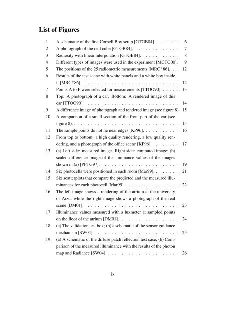
List <strong>of</strong> Figures<br />
1 A schematic <strong>of</strong> the first Cornell Box setup [GTGB84]. . . . . . . 6<br />
2 A photograph <strong>of</strong> the real cube [GTGB84]. . . . . . . . . . . . . . 7<br />
3 Radiosity with linear interpolation [GTGB84]. . . . . . . . . . . . 8<br />
4 Different types <strong>of</strong> images were used in the experiment [MCTG00]. 9<br />
5 The positions <strong>of</strong> the 25 radiometric measurements [MRC + 86]. . . 12<br />
6 Results <strong>of</strong> the test scene with white panels and a white box inside<br />
it [MRC + 86]. . . . . . . . . . . . . . . . . . . . . . . . . . . . . 12<br />
7 Points A to F were selected <strong>for</strong> measurements [TTOO90]. . . . . . 13<br />
8 Top: A photograph <strong>of</strong> a car. Bottom: A rendered image <strong>of</strong> this<br />
car [TTOO90]. . . . . . . . . . . . . . . . . . . . . . . . . . . . 14<br />
9 A difference image <strong>of</strong> photograph and rendered image (see figure 8). 15<br />
10 A comparison <strong>of</strong> a small section <strong>of</strong> the front part <strong>of</strong> the car (see<br />
figure 8). . . . . . . . . . . . . . . . . . . . . . . . . . . . . . . . 15<br />
11 The sample points do not lie near edges [KP96]. . . . . . . . . . . 16<br />
12 From top to bottom: a high quality rendering, a low quality ren-<br />
dering, and a photograph <strong>of</strong> the <strong>of</strong>fice scene [KP96]. . . . . . . . 17<br />
13 (a) Left side: measured image. Right side: computed image; (b)<br />
scaled difference image <strong>of</strong> the luminance values <strong>of</strong> the images<br />
shown in (a) [PFTG97]. . . . . . . . . . . . . . . . . . . . . . . . 19<br />
14 Six photocells were positioned in each room [Mar99]. . . . . . . . 21<br />
15 Six scatterplots that compare the predicted and the measured illu-<br />
minances <strong>for</strong> each photocell [Mar99]. . . . . . . . . . . . . . . . 22<br />
16 The left image shows a rendering <strong>of</strong> the atrium at the university<br />
<strong>of</strong> Aizu, while the right image shows a photograph <strong>of</strong> the real<br />
scene [DM01]. . . . . . . . . . . . . . . . . . . . . . . . . . . . 23<br />
17 Illuminance values measured with a luxmeter at sampled points<br />
on the floor <strong>of</strong> the atrium [DM01]. . . . . . . . . . . . . . . . . . 24<br />
18 (a) The validation test box; (b) a schematic <strong>of</strong> the sensor guidance<br />
mechanism [SW04]. . . . . . . . . . . . . . . . . . . . . . . . . 25<br />
19 (a) A schematic <strong>of</strong> the diffuse patch reflection test case; (b) Com-<br />
parison <strong>of</strong> the measured illuminance with the results <strong>of</strong> the photon<br />
map and Radiance [SW04]. . . . . . . . . . . . . . . . . . . . . . 26<br />
ix


