Usability of Digital Cameras for Verifying Physically Based ...
Usability of Digital Cameras for Verifying Physically Based ...
Usability of Digital Cameras for Verifying Physically Based ...

You also want an ePaper? Increase the reach of your titles
YUMPU automatically turns print PDFs into web optimized ePapers that Google loves.
(a) (b)<br />
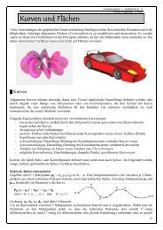
Figure 18: (a) The validation test box; (b) a schematic <strong>of</strong> the sensor guidance<br />
mechanism [SW04].<br />
able to correct the specifications <strong>of</strong> the manufacturer by a maintenance factor. The<br />
inside <strong>of</strong> the box was covered with heavy molleton, which was nearly lambertian.<br />
Nevertheless, the discrepancy between the heavy molleton and a perfectly diffuse<br />
lambertian surface was significant. There<strong>for</strong>e, an extensive BRDF measurement<br />
<strong>of</strong> the molleton was inevitable. In order to be able to validate caustics as well,<br />
a so-called sandblasted aluminium light shelf was attached at the open side <strong>of</strong><br />
the box. The BRDFs <strong>of</strong> the molleton and the aluminium were obtained using a<br />
goniophotometer (see appendix B.7).<br />
Schregle and Wienold did two different kinds <strong>of</strong> case studies. First, compon-<br />
ent case studies were done, where individual components <strong>of</strong> the rendering sys-<br />
tem were tested. After this, compound case studies were per<strong>for</strong>med which were<br />
combinations <strong>of</strong> different component case studies. Lighting simulations were per-<br />
<strong>for</strong>med using photon maps and the Radiance engine to be able to compare <strong>for</strong>ward<br />
and backward raytracing methods.<br />
Four different case studies are presented in this paper: diffuse patch reflec-<br />
tion, light shelf caustics, diffuse interreflection, and a combination <strong>of</strong> light shelf<br />
caustics and diffuse interreflection. For the first test case, two patches <strong>of</strong> light gray<br />
molleton where placed between the floor sensor tracks. The resulting illuminance<br />
was measured on the ceiling. To validate the accuracy <strong>of</strong> their measurements,<br />
Schregle and Wienold analytically calculated the theoretical result <strong>of</strong> the diffuse<br />
reflection. A schematic <strong>of</strong> the inside <strong>of</strong> the box can be seen in figure 19a.<br />
A comparison <strong>of</strong> the measured values and the results <strong>of</strong> the Radiance and<br />
25