K Control panel
K Control panel
K Control panel

Create successful ePaper yourself
Turn your PDF publications into a flip-book with our unique Google optimized e-Paper software.
ENGLISH<br />
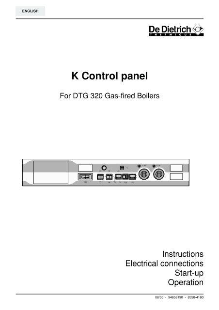
K <strong>Control</strong> <strong>panel</strong><br />
For DTG 320 Gas-fired Boilers<br />
30<br />
0<br />
l<br />
6A<br />
Instructions<br />
Electrical connections<br />
Start-up<br />
Operation<br />
08/00 - 94858190 - 8358-4160
CONFORMITY / MARKING<br />
This product complies with the requirements of the<br />
following European Directives and Standards:<br />
- 73/23 CEE Low voltage directive<br />
Relevant standard: EN 60.335.1.<br />
- 89.336 CEE Electromagnetic Compatibility Directive<br />
Relevant standards: EN 50.081.1 / EN 50.082.1 /<br />
EN 55.014.<br />
CONTENTS<br />
1. INTRODUCTION .................................................................................................................................................. 3<br />
2. GENERAL ........................................................................................................................................................... 3<br />
2.1 Overview ...................................................................................................................................................... 3<br />
2.2 Description ................................................................................................................................................... 4<br />
2.3 Operating principle ....................................................................................................................................... 5<br />
3. ELECTRICAL CONNECTIONS ........................................................................................................................... 6<br />
3.1 Installation without optional features ............................................................................................................ 6<br />
3.2 Installation with optional MB2 domestic hot water module .......................................................................... 7<br />
3.2.1 Fitting the MB2 module ....................................................................................................................... 7<br />
3.2.2 Connections ........................................................................................................................................ 8<br />
3.3 Installation with optional SV-matic weather compensator .......................................................................... 10<br />
3.3.1 Fitting the SV-matic weather compensator ....................................................................................... 10<br />
3.3.2 Connections ...................................................................................................................................... 11<br />
3.4 Installation with optional cascade board .................................................................................................... 13<br />
3.5 Connecting the safety thermostat alarm indicator ..................................................................................... 13<br />
3.6 Connecting the hour run meter(s) .............................................................................................................. 13<br />
3.7 Connecting the flue gas thermometer ........................................................................................................ 14<br />
3.8 Connecting the burner + options ................................................................................................................ 14<br />
4. SKELETON DIAGRAMS.................................................................................................................................... 15<br />
4.1 Skeleton diagram 2 stages without optional features ................................................................................ 15<br />
4.2 Skeleton diagram 2 stages with optional domestic hot water priority module ........................................... 16<br />
4.3 Skeleton diagram 2 stages with optional regulator .................................................................................... 17<br />
4.4 Skeleton diagram 2 stages with optional cascade board ........................................................................... 18<br />
5. START-UP AND OPERATION .......................................................................................................................... 19<br />
5.1 <strong>Control</strong> <strong>panel</strong> without optional features ...................................................................................................... 19<br />
5.2 <strong>Control</strong> <strong>panel</strong> with optional MB2 domestic hot water module .................................................................... 20<br />
5.3 <strong>Control</strong> <strong>panel</strong> with optional SV-matic weather compensator ..................................................................... 22<br />
5.4 <strong>Control</strong> <strong>panel</strong> with optional cascade board ................................................................................................ 24
1. INTRODUCTION<br />
The K control <strong>panel</strong> is fitted on the DE DIETRICH<br />
DTG 320 S or DTG 320 Eco.NOx boilers.<br />
2. GENERAL<br />
2.1 Overview<br />
The K control <strong>panel</strong> allows operating a 2-stage boiler<br />
(DTG 320 S or DTG 320 Eco.NOx).<br />
It may be fitted along with various optional features:<br />
- MB2 domestic hot water priority module<br />
or<br />
- SV-matic weather compensator for 2-stage burners,<br />
regulating the burner only or the burner with one mixing<br />
valve, for heating only or for heating and domestic hot<br />
water<br />
or<br />
- Cascade board (package AD 135). The cascade<br />
board is used in installations where one or more<br />
boilers (up to 9) fitted with K contol <strong>panel</strong>s are<br />
controlled by a boiler fitted with a Diematic-m Delta<br />
control <strong>panel</strong> for cascaded operation of the entire<br />
boilers system.<br />
The connection between the boilers is carried out via<br />
the 8 m long connecting cable supplied with the<br />
AD 135 package.<br />
- A 12 m long cable - package AD 134 - is available as<br />
an option if required.<br />
- Hour run meter(s) (package BG 40)<br />
- Flue gas thermometer (package BP 28).<br />
3<br />
The electrical connections of the boiler shall<br />
be performed by a qualified professionnal<br />
only.<br />
Strict compliance with these connecting,<br />
starting up and operating instrucions is a<br />
precondition for the correct operation of the<br />
boiler.
2.2 Description<br />
2 allures<br />
1. Three-position switch Auto / Manual / STB TEST<br />
1.1 Boilers fitted with a cascade board<br />
(package AD 135)<br />
11 8 9 1 10 13 6<br />
AUTO: automatic position<br />
This position allows automatic operation of the<br />
installation under the control of the Diematic-m<br />
Delta regulator.<br />
Manual : manual position<br />
The boiler disregards the commands coming<br />
from the cascade board. It is regulated by the<br />
boiler thermostats (item 5)<br />
1.2 Other cases<br />
- either in manual position : boilers not fitted<br />
with a room thermostat or a SV-matic weather<br />
compensator.<br />
- or in AUTO position: boilers fitted with a room<br />
thermostat or a SV-matic weather compensator.<br />
The manual position does not allow<br />
switching off the regulator.<br />
STB Test: temporary action to test the safety<br />
thermostat:<br />
Press the TEST STB switch and set the pump shutoff<br />
switch 2 to the "Summer" position.<br />
2. Double switch Burner/Heating pump:<br />
This double switch controls the burner and the<br />
heating pump.<br />
In the "Winter" position, both heating and<br />
domestic hot water are operating.<br />
In the "Summer" position, only domestic hot water<br />
is operating (if a hot water tank is connected).<br />
If the boiler is fitted with a SV-matic weather<br />
compensator or is part of a cascaded installation,<br />
both switches must be left on the Winter<br />
position.<br />
7<br />
30<br />
3<br />
0<br />
l<br />
4<br />
2<br />
6A<br />
14<br />
3. Main ON/OFF switch<br />
4. Locations for hour run meters<br />
for the first and second stages (BG 40 option)<br />
5. Boiler thermostats (adjustment range from 40°C to 90°C):<br />
A factory-set stop limits the maximum temperature<br />
to 75°C. This stop may be moved if necessary (see<br />
chapter 5.1).<br />
6. Stage 1 or stage 2 indicators:<br />
These indicators only light up if the relevant<br />
thermostat or the regulator require heating and if<br />
the safety contact is closed.<br />
7. Boiler thermometer<br />
8. Location for the flue gas thermometer<br />
(Optional package BP 28)<br />
9. Safety thermostat with manual reset<br />
(cut-off temperature: 110°C).<br />
10. 4 A circuit-breaker<br />
with delayed action and manual reset.<br />
11. Location for the optional MB2 domestic hot<br />
water priority module or SV-matic weather<br />
compensator<br />
13. Switch selecting the number of burner stages<br />
14. Burner alarm indicator<br />
5<br />
4<br />
8502N008
2.3 Operating principle<br />
Boiler regulation<br />
Boiler regulation may be performed:<br />
- either by the boiler thermostats,<br />
- or by the SV-matic weather compensator, if any<br />
(optional),<br />
- or by the DIEMATIC-m Delta control <strong>panel</strong> in case of<br />
a cascaded installation.<br />
If the boiler is fitted with a SV-matic weather compensator<br />
or is controlled by a DIEMATIC-m Delta control<br />
<strong>panel</strong>, the boiler temperature is modulated by the<br />
regulator acting on the burner according to the outside<br />
temperature. In this case, the boiler thermostats are set<br />
to the maximum position. Operating safety is provided<br />
by the safety thermostat with manual reset.<br />
If the boiler is fitted with a SV-matic weather compensator<br />
controlling a valve, the heating temperature is<br />
modulated by the regulator acting on the burner and on<br />
the motorised mixing valve according to the outside<br />
temperature.<br />
For a cascaded installation controlled by a boiler fitted<br />
with a DIEMATIC-m Delta control <strong>panel</strong>, refer to the<br />
instructions supplied with the DIEMATIC-m Delta control<br />
<strong>panel</strong>.<br />
5<br />
Domestic hot water regulation<br />
With the optional MB2 domestic hot water priority<br />
module or the Type B SV-matic weather compensator:<br />
When the domestic hot water is being reheated, the<br />
burner and the load pump are started while the<br />
heating pump is stopped. The boiler temperature is<br />
then regulated by the limiter thermostat integrated in<br />
the MB2 module or in the SV-matic weather compensator.<br />
Once the need for hot water is met, the burner is<br />
turned off. The load pump continues operating for 4<br />
minutes after the burner stops (This delay is adjustable<br />
from 30 sec to 15 min). This allows using the residual<br />
heat accumulated in the heating elements and complete<br />
heating the tank, especially in summer.<br />
For a cascaded installation controlled by a boiler fitted<br />
with a DIEMATIC-m Delta control <strong>panel</strong>, refer to the<br />
instructions supplied with the DIEMATIC-m Delta control<br />
<strong>panel</strong>.
3. ELECTRICAL CONNECTIONS<br />
The electrical wiring has been thoroughly<br />
checked in the factory and the internal<br />
connections of the control <strong>panel</strong> must in no<br />
case be modified.<br />
3.1 Installation without optional features<br />
All the connections shall be made to the terminal block provided<br />
for that purpose in the boiler control <strong>panel</strong>.<br />
Proceed as follows to open the control <strong>panel</strong>:<br />
➀ Remove the boiler top <strong>panel</strong>.<br />
➁ Unhook the intermediate front <strong>panel</strong>.<br />
➂ Remove the upper front <strong>panel</strong>.<br />
Make the connections as shown opposite.<br />
1<br />
7<br />
8<br />
6<br />
9<br />
5<br />
4<br />
3<br />
7<br />
8<br />
6<br />
9<br />
5<br />
4<br />
3<br />
2<br />
3<br />
8358N024<br />
6<br />
The electrical connections shall be made in compliance with<br />
the instructions given in the electrical diagrams supplied with<br />
the device and the guidelines provided in the manual.<br />
The electrical connection must comply with the standards in<br />
force. The device shall be powered by a circuit with an<br />
omnipole switch with an opening distance exceeding 3<br />
mm. Earthing shall comply with the standard in force.<br />
POMPE DE RECYCLAGE<br />
KESSELKREISPUMPE<br />
SHUNT PUMP<br />
1 2 3 4 5 6 7 8 9 10 11 12 13 14 15 16<br />
L N L N L N L N L N<br />
ALI<br />
CS VA - TS VS<br />
230V 50Hz<br />
ALIMENTATION<br />
STROMZUFÜHR<br />
MAIN SUPPLY<br />
6<br />
VOYANT ALARME TS<br />
TS ALARMLEUCHTE<br />
TS ALARM INDICATOR<br />
SAFETY CONTACT<br />
VOYANT ALARME TS<br />
TS ALARMLEUCHTE<br />
TS ALARM INDICATOR<br />
VANNE DE SECURITE<br />
SICHERHEITSVENTIL<br />
SAFETY VALVE<br />
CONTACT DE SECURITE<br />
SICHERHEITSKONTACT<br />
➃ Remove the connection board cover.<br />
➄ After removing the 4 fastening screws, tilt the front<br />
cover to open the control <strong>panel</strong>.<br />
➅ Fasten the cables to the board supporting plate using<br />
cable clamps (6 cable clamps supplied in a bag) that<br />
are to be assembled as shown opposite.<br />
230V<br />
Main supply<br />
3x 0,75 mm 2 mini.<br />
Heating<br />
pump<br />
3x 0,75 mm 2 mini.<br />
230V 50Hz<br />
ALI<br />
CS VA-TS VS<br />
L N L N L N<br />
L N L N<br />
1 2 3 4 5 6 7 8 9 10 11 12 13 14 15 16<br />
4<br />
5<br />
8502N127<br />
8502N086
3.2 Installation with optional MB2 domestic hot water module<br />
4<br />
3<br />
2<br />
1<br />
5<br />
6<br />
7<br />
8<br />
3.2.1. Fitting the MB2 module<br />
The MB2 module is to be fitted in the left-hand front<br />
side of the control <strong>panel</strong>.<br />
- Cut off the front <strong>panel</strong> skin using a cutter.<br />
- Cut off the metal cover along the micro-joints using<br />
pliers.<br />
30<br />
0<br />
l<br />
7<br />
6A<br />
8502N088<br />
The setting and operating instructions for<br />
the MB2 module can be found in the<br />
manual supplied with the option.<br />
8502N089<br />
8502N090
3.2.2. Connections<br />
- Connect module connector B to connector C marked<br />
«MODULE ECS» (DHW MODULE) coming from the<br />
boiler control <strong>panel</strong>, after removing bridge plug D.<br />
- Connect the loading pump to the three-wire connecting<br />
block at the rear of the module, taking care to connect<br />
the phase (L), neutral (N) and earth ( ) wires correctly.<br />
- Connect the tank sensor to the two-wire connecting<br />
block marked «SB» at the rear of the module.<br />
Then:<br />
- Insert the probe E of the limiter thermostat in the boiler<br />
pocket.<br />
- Insert the tank sensor in the pocket of the domestic<br />
hot water tank.<br />
Note:<br />
If the tank is already fitted with a thermostat, it will not<br />
be used. Replace the tank thermostat bulb with the<br />
tank sensor.<br />
- Fasten the module onto the front of the control <strong>panel</strong><br />
with the help of the 2 Philips head screws of the<br />
module.<br />
- Proceed with the other connections.<br />
8<br />
DHW MODULE<br />
MODULE E.C.S<br />
BOILERVORRANGSCHALTUNG<br />
SB<br />
E<br />
SB<br />
C<br />
MB<br />
D<br />
T<br />
1<br />
2 3 4 5 6<br />
B<br />
MINI MAXI<br />
T=0<br />
7<br />
8<br />
TEMPO<br />
L N<br />
MB<br />
In the boiler<br />
pocket<br />
L N<br />
Tank sensor Load pump<br />
1<br />
2 3 4 5 6<br />
7<br />
8<br />
8502N091<br />
8801N112<br />
8502N092
All the connections shall be made to the terminal block provided<br />
for that purpose in the boiler control <strong>panel</strong>.<br />
Proceed as follows to open the control <strong>panel</strong>:<br />
➀ Remove the boiler top <strong>panel</strong>.<br />
➁ Unhook the intermediate front <strong>panel</strong>.<br />
➂ Remove the upper front <strong>panel</strong>.<br />
Make the connections as shown opposite.<br />
1<br />
The very low voltage sensor cables must<br />
be separated from the 230 V main supply<br />
cables in order to avoid electromagnetic<br />
interference problems.<br />
Inside the boiler<br />
- Boilers with one cable channel:<br />
Place the 230 V main supply cables on one side of the<br />
cable channel and the sensor cables on the other. The<br />
cables shall be held in place on either side using<br />
plastic ties.<br />
- Boilers with two cable channels:<br />
Place the 230 V main supply cables in one cable<br />
channel and the sensor cables in the other. The cables<br />
shall be held in place using plastic ties.<br />
7<br />
8<br />
6<br />
9<br />
5<br />
4<br />
3<br />
7<br />
8<br />
6<br />
9<br />
5<br />
4<br />
3<br />
2<br />
3<br />
8358N024<br />
9<br />
POMPE DE RECYCLAGE<br />
KESSELKREISPUMPE<br />
SHUNT PUMP<br />
1 2 3 4 5 6 7 8 9 10 11 12 13 14 15 16<br />
L N L N L N L N L N<br />
ALI<br />
CS VA - TS VS<br />
230V 50Hz<br />
ALIMENTATION<br />
STROMZUFÜHR<br />
MAIN SUPPLY<br />
6<br />
VOYANT ALARME TS<br />
TS ALARMLEUCHTE<br />
➃ Remove the connection board cover.<br />
➄ After removing the 4 fastening screws, tilt the front<br />
cover to open the control <strong>panel</strong>.<br />
➅ Fasten the cables to the board supporting plate using<br />
cable clamps (6 cable clamps supplied in a bag) that<br />
are to be assembled as shown opposite.<br />
230V<br />
Main supply<br />
3x 0,75 mm 2 mini.<br />
Outside the boiler<br />
TS ALARM INDICATOR<br />
SAFETY CONTACT<br />
VOYANT ALARME TS<br />
TS ALARMLEUCHTE<br />
TS ALARM INDICATOR<br />
VANNE DE SECURITE<br />
SICHERHEITSVENTIL<br />
SAFETY VALVE<br />
CONTACT DE SECURITE<br />
SICHERHEITSKONTACT<br />
Heating<br />
pump<br />
3x 0,75 mm 2 mini.<br />
230V 50Hz<br />
ALI<br />
CS VA-TS VS<br />
L N L N L N<br />
L N L N<br />
1 2 3 4 5 6 7 8 9 10 11 12 13 14 15 16<br />
Use 2 cable ducts or channels with a minimum<br />
distance of 10 cm between them.<br />
Failure to comply with these instuctions may lead<br />
to interference and regulator malfunction, or even<br />
damage the electronic circuitry.<br />
4<br />
5<br />
8502N127<br />
8502N086
3.3 Installation with optional SV-matic weather compensator<br />
1,5<br />
1<br />
0,5<br />
2 2,5<br />
3<br />
3,5<br />
1<br />
0,5<br />
1,5 2<br />
2,5<br />
3<br />
3,5<br />
50<br />
40<br />
60<br />
30<br />
20 80<br />
14<br />
2<br />
2<br />
14<br />
26<br />
1 2 3 4 5 6 7<br />
1...7 H<br />
Prog.<br />
3.3.1 Fitting the SV-matic weather compensator<br />
OFF<br />
ON<br />
M<br />
R<br />
232 DB<br />
The SV-matic weather compensator is to be fitted in the<br />
left-hand front side of the control <strong>panel</strong>.<br />
- Cut off the front <strong>panel</strong> skin using a cutter.<br />
- Cut off the metal cover along the micro-joints using<br />
pliers.<br />
30<br />
0<br />
l<br />
10<br />
6A<br />
8502N093<br />
Optionnal additional wiring (package AV 106)<br />
is required with the SV-matic weather<br />
compensator.<br />
8502N089<br />
8502N090
3.3.2 Connections<br />
All the connections shall be made to the terminal block provided<br />
for that purpose in the boiler control <strong>panel</strong>.<br />
Proceed as follows to open the control <strong>panel</strong>:<br />
➀ Remove the boiler top <strong>panel</strong>.<br />
➁ Unhook the intermediate front <strong>panel</strong>.<br />
➂ Remove the upper front <strong>panel</strong>.<br />
Installing the additional wiring package AV 106<br />
1<br />
- With the help of the two screws B supplied for that purpose,<br />
fasten the the connecting strip support A (supplied<br />
with the additional wiring package AV 106) in the location<br />
provided for that purpose in the control <strong>panel</strong>.<br />
- Plug the 9-pin connector D of the cable form into<br />
connector E, marked «REGULATION» (REGULA-<br />
TOR),which is prepared in the control <strong>panel</strong>, after<br />
removing bridge plug C.<br />
7<br />
8<br />
6<br />
9<br />
5<br />
4<br />
3<br />
7<br />
8<br />
6<br />
9<br />
5<br />
4<br />
3<br />
2<br />
3<br />
8358N024<br />
11<br />
➃ Remove the connection board cover.<br />
➄ After removing the 4 fastening screws, tilt the front<br />
cover to open the control <strong>panel</strong>.<br />
➅ Fasten the cables to the board supporting plate using<br />
cable clamps (6 cable clamps supplied in a bag) that<br />
are to be assembled as shown opposite.<br />
C<br />
E<br />
1 2 3 4 5 6 7 8 9 10 11 12 13 14 15 16<br />
L N L N L N L N L N<br />
ALI<br />
CS VA - TS VS<br />
230V 50Hz<br />
D<br />
POMPE DE RECYCLAGE<br />
KESSELKREISPUMPE<br />
SHUNT PUMP<br />
ALIMENTATION<br />
STROMZUFÜHR<br />
MAIN SUPPLY<br />
6<br />
VOYANT ALARME TS<br />
TS ALARMLEUCHTE<br />
TS ALARM INDICATOR<br />
SAFETY CONTACT<br />
VOYANT ALARME TS<br />
TS ALARMLEUCHTE<br />
TS ALARM INDICATOR<br />
VANNE DE SECURITE<br />
SICHERHEITSVENTIL<br />
SAFETY VALVE<br />
CONTACT DE SECURITE<br />
SICHERHEITSKONTACT<br />
RED<br />
A<br />
B<br />
4<br />
5<br />
8502N127<br />
BLUE<br />
8502N094
Carry out the electrical connections.<br />
N L N<br />
AF<br />
SONDE SONDE SONDE SONDE<br />
COMMANDE A DISTANCE<br />
FERNBEDIENUNG<br />
1 2 3 4<br />
1 2 3 4 5 6 7 8 9 10 11 12 13 14 15 16 17 18 19<br />
8502N095<br />
Connecting strip for the connection of the sensors<br />
and the controls of the SV-matic weather compensator.<br />
Refer to the instructions supplied with the regulator and<br />
any remote control used.<br />
Inside the boiler<br />
The very low voltage sensor cables must<br />
be separated from the 230 V main supply<br />
cables in order to avoid electromagnetic<br />
interference problems.<br />
- Boilers with one cable channel:<br />
Place the 230 V main supply cables on one side of the<br />
cable channel and the sensor cables on the other. The<br />
cables shall be held in place on either side using<br />
plastic ties.<br />
- Boilers with two cable channels:<br />
Place the 230 V main supply cables in one cable<br />
channel and the sensor cables in the other. The cables<br />
shall be held in place using plastic ties.<br />
- Bring the blue and red connectors out through the<br />
opening in the control <strong>panel</strong>.<br />
- Close the control <strong>panel</strong>.<br />
- Plug both connectors onto the back of the regulator:<br />
● blue connector in the blue socket,<br />
● red connector in the red socket.<br />
- Push the casing into the front of the control <strong>panel</strong> and<br />
fasten it with the two plastic screws (1/4 turn clockwise)<br />
located on the front side of the regulator.<br />
12<br />
230V<br />
Main supply<br />
3x 0,75 mm 2 mini.<br />
Outside the boiler<br />
3x 0,75 mm 2 mini.<br />
230V 50Hz<br />
ALI<br />
CS VA-TS VS<br />
L N L N L N<br />
L N L N<br />
1 2 3 4 5 6 7 8 9 10 11 12 13 14 15 16<br />
8502N086<br />
Use 2 cable ducts or channels with a minimum<br />
distance of 10 cm between them.<br />
Failure to comply with these instuctions may lead<br />
to interference and regulator malfunction, or even<br />
damage the electronic circuitry.<br />
BLUE<br />
Heating<br />
pump<br />
2,5<br />
1,0<br />
3<br />
0,5<br />
3,5<br />
1,5 2<br />
2,5<br />
1,0<br />
3<br />
0,5<br />
3,5<br />
14 26<br />
20<br />
14<br />
50<br />
40<br />
60<br />
30<br />
20 80<br />
8<br />
1 2 3 4 5 6 7<br />
1...7 - +<br />
Prog<br />
RED<br />
331 DB<br />
1/4<br />
8502N096
3.4 Installation with optional cascade board<br />
Refer to the instructions supplied with the cascade board<br />
(package AD 135).<br />
3.5 Connecting the safety thermostat alarm indicator<br />
Safety thermostat<br />
alarm indicator<br />
2x 0,75 mm 2 mini.<br />
230V 50Hz<br />
ALI<br />
CS VA-TS VS<br />
L N L N L N<br />
L N L N<br />
1 2 3 4 5 6 7 8 9 10 11 12 13 14 15 16<br />
8502N097<br />
3.6 Connecting the hour run meter(s) (package BG 40)<br />
One or two optional hour run meters (stages 1 and 2)<br />
may be fitted to the front of the control <strong>panel</strong>.<br />
Proceed as follows:<br />
- Cut the cover off with a cutter along the edges of the<br />
coloured rectangle.<br />
- Pull out the 2 wires prepared in the control <strong>panel</strong>.<br />
- Connect the wires to the hour run meter (the wires<br />
are interchangeable).<br />
- Clip the hour run meter into the control <strong>panel</strong>.<br />
If the burner used is a one-stage burner, the counter<br />
displays the burner operating time.<br />
If the burner used is a two-stage burner, the counters<br />
display the operating time of each stage.<br />
13<br />
7<br />
6 5 4 3<br />
9 8<br />
2<br />
1<br />
7<br />
6 5 4 3<br />
9 8<br />
2<br />
1<br />
8502N098
3.7 Connecting the flue gas thermometer (package BP 28)<br />
An optional flue gas thermometer may be fitted to the<br />
front of the control <strong>panel</strong>.<br />
Proceed as follows:<br />
- Cut the cover off with a cutter along the edges of the<br />
coloured rectangle.<br />
- Clip the thermometer into the opening.<br />
- Bring the sensor to the back of the boiler via the cable<br />
channel and insert it in the flue gas pipe.<br />
3.8 Connecting the burner<br />
Connect the following connectors below the control <strong>panel</strong>:<br />
1. Ignition device circuit<br />
2. Gas pressure switch<br />
3. Gas valves circuit<br />
4. Leak proofing system (option DP 92)<br />
The leak proofing system DP 92 is obligatory<br />
in Austria on boilers DTG 320-20<br />
(Nominal power input ≥ 350 kW)<br />
14<br />
7<br />
6 5 4 3<br />
9 8<br />
2<br />
1<br />
1 2 3<br />
4<br />
7<br />
6 5 4 3<br />
9 8<br />
2<br />
1<br />
8502N099<br />
8358N013
4. SKELETON DIAGRAMS<br />
4.1 Skeleton diagram of installations without optional features<br />
VA-SCS<br />
17<br />
1b<br />
1<br />
BPR-VA<br />
SI<br />
1a<br />
1a<br />
ZG<br />
4 3<br />
7 2<br />
1<br />
1<br />
1a<br />
L<br />
1<br />
BA<br />
DGAI 73<br />
SCS<br />
5 7<br />
1 2<br />
X13 5 4 X2 10 X3<br />
2<br />
1<br />
TAF<br />
1<br />
1<br />
3<br />
1<br />
6<br />
6<br />
5<br />
5<br />
2<br />
2 4<br />
FA<br />
2<br />
ECS<br />
8<br />
6<br />
RG<br />
CA<br />
7<br />
8<br />
CCE<br />
6<br />
CCE<br />
DJ4A TI<br />
1 2 1 3<br />
1<br />
1 TCH1<br />
CCE 2 PSG<br />
ECS<br />
3 1<br />
6<br />
7<br />
RG 3 2<br />
1<br />
9<br />
P<br />
9 7<br />
ZT<br />
1<br />
1<br />
1a 1b<br />
ZEH<br />
2<br />
1a 1b<br />
CA ECS CA<br />
CCE<br />
11<br />
12 4 1<br />
5<br />
CA<br />
CA<br />
6<br />
1<br />
4<br />
1<br />
9<br />
1<br />
TCH2<br />
2<br />
7<br />
4<br />
2<br />
2<br />
9<br />
8<br />
3<br />
2<br />
ZT<br />
2a 2b<br />
1a<br />
RG<br />
4 5<br />
TS 1<br />
3<br />
2<br />
BA 10<br />
3 8<br />
ZB<br />
1<br />
14<br />
CS<br />
2b<br />
CA<br />
13<br />
15<br />
15<br />
4 5 6<br />
(B)<br />
1 1 4<br />
VS VG VP<br />
1 2<br />
1<br />
11<br />
1<br />
7 1 6<br />
BA<br />
CO<br />
1a<br />
VB2 CH2<br />
14<br />
1<br />
BA<br />
4<br />
1<br />
CH1<br />
VB1<br />
1<br />
1<br />
h<br />
h<br />
VS<br />
2<br />
2<br />
5<br />
2<br />
1b<br />
5<br />
2<br />
2<br />
2<br />
A<br />
2<br />
P2<br />
2<br />
7 8 9<br />
15<br />
2a<br />
ZEH<br />
2<br />
7 BA BA 12<br />
1a<br />
VA-TS<br />
1b<br />
CCE**<br />
6 BA<br />
2 BA 13<br />
2 4<br />
TI<br />
BA<br />
5<br />
ZG<br />
2a 2<br />
N<br />
2<br />
BA<br />
8358N055<br />
VP Main valve<br />
VS Safety valve<br />
ZB Burner switch<br />
ZEH Summer/Winter switch<br />
ZG Main switch<br />
ZT Test switch<br />
TCH1 Boiler thermostat<br />
1st stage<br />
TCH2 Boiler thermostat<br />
2nd stage<br />
TI Isolating transformer<br />
TS Safety thermostat<br />
VA-TS Safety thermostat alarm<br />
indicator<br />
VB1 Stage 1 operating indicator<br />
VB2 Stage 2 operating indicator<br />
VG Gas valve<br />
ECS Domestic hot water<br />
FA EMI suppressor<br />
L Phase<br />
N Neutral<br />
P2 Shunt pump<br />
PSG Gas pressure switch<br />
R Relay<br />
RG Regulator<br />
SCS Safety control box<br />
SI Ionisation probe<br />
TAF Draught diverter thermostat<br />
A Heating pump<br />
AE Electrical ignition device<br />
B Burner<br />
BA Connecting strip<br />
BPR-VA Reset button and<br />
burner alarm indicator<br />
CA Cascade<br />
CCE Leak proofing system<br />
CO Flue damper<br />
CS Safety contact<br />
Dj4A 4 A circuit-breaker
4.2 Skeleton diagram with optional domestic hot water priority module<br />
VA-SCS<br />
17<br />
1b<br />
1<br />
BPR-VA<br />
SI<br />
1a<br />
1a<br />
ZG<br />
4 3<br />
7 2<br />
1<br />
1<br />
1a<br />
L<br />
1<br />
BA<br />
DGAI 73<br />
SCS<br />
5 7<br />
1 2<br />
X13 5 4 X2 10 X3<br />
2<br />
1<br />
TAF<br />
1<br />
1<br />
3<br />
1<br />
6<br />
6<br />
5<br />
5<br />
2<br />
2 4<br />
FA<br />
2<br />
ECS<br />
8<br />
6<br />
RG<br />
CA<br />
7<br />
8<br />
CCE<br />
6<br />
CCE<br />
DJ4A TI<br />
1 2 1 3<br />
1<br />
1 TCH1<br />
CCE 2 PSG<br />
ECS<br />
3 1<br />
6<br />
7<br />
RG 3 2<br />
1<br />
9<br />
P<br />
9 7<br />
ZT<br />
1<br />
1<br />
1a 1b<br />
ZEH<br />
2<br />
1a 1b<br />
CA ECS CA<br />
CCE<br />
11<br />
12 4 1<br />
5<br />
CA<br />
CA<br />
6<br />
1<br />
4<br />
1<br />
9<br />
1<br />
TCH2<br />
2<br />
7<br />
4<br />
2<br />
2<br />
9<br />
8<br />
3<br />
2<br />
ZT<br />
2a 2b<br />
1a<br />
RG<br />
4 5<br />
TS 1<br />
3<br />
2<br />
BA 10<br />
3 8<br />
ZB<br />
1<br />
14<br />
CS<br />
2b<br />
13<br />
15<br />
4 5 6<br />
(B)<br />
1 1 4<br />
VS VG VP<br />
1 2<br />
1<br />
11<br />
1<br />
7 1 6<br />
BA<br />
CO<br />
1a<br />
VB2 CH2<br />
14<br />
BA<br />
4<br />
1<br />
1<br />
1<br />
VS<br />
2<br />
2<br />
5<br />
1b<br />
5<br />
2<br />
2<br />
2<br />
A<br />
2<br />
P2<br />
2<br />
7 8 9<br />
15<br />
2a<br />
ZEH<br />
2<br />
7 BA BA 12<br />
1a<br />
VA-TS<br />
1b<br />
CCE**<br />
6 BA<br />
2 BA 13<br />
16<br />
CA<br />
1<br />
CH1<br />
VB1<br />
h<br />
h<br />
2<br />
BA<br />
5<br />
2 4<br />
TI<br />
ZG<br />
2a 2<br />
N<br />
2<br />
BA<br />
8358N058<br />
VP Main valve<br />
VS Safety valve<br />
ZB2 Burner switch<br />
ZEH Summer/Winter switch<br />
ZG Main switch<br />
ZT Test switch<br />
TCH1 Boiler thermostat<br />
1st stage<br />
TCH2 Boiler thermostat<br />
2nd stage<br />
TI Isolating transformer<br />
TS Safety thermostat<br />
VA-TS Safety thermostat alarm<br />
indicator<br />
VB1 Stage 1 operating indicator<br />
VB2 Stage 2 operating indicator<br />
VG Gas valve<br />
ECS Domestic hot water<br />
FA EMI suppressor<br />
L Phase<br />
N Neutral<br />
P2 Shunt pump<br />
PSG Gas pressure switch<br />
RG Regulator<br />
SCS Safety control box<br />
SI Ionisation probe<br />
TAF Draught diverter thermostat<br />
A Heating pump<br />
AE Electrical ignition device<br />
B Burner<br />
BA Connecting strip<br />
BPR-VA Reset button and<br />
burner alarm indicator<br />
CA Cascade<br />
CCE Leak proofing system<br />
CO Flue damper<br />
CS Safety contact<br />
Dj4A 4 A circuit-breaker
4.3 Skeleton diagram with optional regulator<br />
VA-SCS<br />
17<br />
1b<br />
1<br />
BPR-VA<br />
SI<br />
1a<br />
1a<br />
ZG<br />
4 3<br />
7 2<br />
1<br />
1<br />
1a<br />
L<br />
1<br />
BA<br />
DGAI 73<br />
SCS<br />
5 7<br />
1 2<br />
X13 5 4 X2 10 X3<br />
2<br />
1<br />
TAF<br />
1<br />
1<br />
3<br />
1<br />
6<br />
6<br />
5<br />
5<br />
2<br />
2 4<br />
FA<br />
2<br />
ECS<br />
8<br />
6<br />
RG<br />
CA<br />
7<br />
8<br />
CCE<br />
6<br />
CCE<br />
DJ4A TI<br />
1 2 1 3<br />
1<br />
1 TCH1<br />
CCE 2 PSG<br />
ECS<br />
3 1<br />
6<br />
7<br />
RG 3 2<br />
1<br />
9<br />
P<br />
9 7<br />
ZT<br />
1<br />
1<br />
1a 1b<br />
ZEH<br />
2<br />
1a 1b<br />
CA ECS CA<br />
CCE<br />
11<br />
12 4 1<br />
5<br />
CA<br />
CA<br />
6<br />
1<br />
4<br />
1<br />
9<br />
1<br />
TCH2<br />
2<br />
7<br />
4<br />
2<br />
2<br />
9<br />
8<br />
3<br />
2<br />
ZT<br />
2a 2b<br />
1a<br />
RG<br />
4 5<br />
TS 1<br />
3<br />
2<br />
BA 10<br />
3 8<br />
ZB<br />
1<br />
14<br />
CS<br />
2b<br />
17<br />
CA<br />
13<br />
15<br />
4 5 6<br />
(B)<br />
1 1 4<br />
VS VG VP<br />
1 2<br />
1<br />
11<br />
1<br />
7 1 6<br />
BA<br />
CO<br />
1a<br />
VB2 CH2<br />
14<br />
1<br />
BA<br />
4<br />
1<br />
CH1<br />
VB1<br />
1<br />
1<br />
h<br />
h<br />
VS<br />
2<br />
2<br />
5<br />
2<br />
1b<br />
5<br />
2<br />
2<br />
2<br />
A<br />
2<br />
P2<br />
2<br />
7 8 9<br />
15<br />
2a<br />
ZEH<br />
2<br />
7 BA BA 12<br />
1a<br />
VA-TS<br />
1b<br />
CCE**<br />
6 BA<br />
2 BA 13<br />
2 4<br />
TI<br />
BA<br />
5<br />
ZG<br />
2a 2<br />
N<br />
2<br />
BA<br />
8358N057<br />
ZB2 Burner switch<br />
ZEH Summer/Winter switch<br />
ZG Main switch<br />
ZT Test switch<br />
* Eco.NOx Version<br />
** S Version<br />
TCH2 Boiler thermostat<br />
2nd stage<br />
TI Isolating transformer<br />
TS Safety thermostat<br />
VA-TS Safety thermostat alarm<br />
indicator<br />
VB1 Stage 1 operating indicator<br />
VB2 Stage 2 operating indicator<br />
VP1 Stage 1 main valve<br />
VP2 Stage 2 main valve<br />
VS Safety indicator<br />
CS Safety contact<br />
Dj4A 4 A circuit-breaker<br />
ECS Domestic hot water<br />
P2 Shunt pump<br />
PSG Gas pressure switch<br />
RG Regulator<br />
SCS Safety control box<br />
SCS2 Ionisation measurement<br />
TAF Draught diverter thermostat<br />
TCH1 Boiler thermostat<br />
1st stage<br />
A Heating pump<br />
AE Electrical ignition device<br />
B Burner<br />
B2 Burner 2nd stage<br />
BPR-VA Reset button and<br />
burner alarm indicator<br />
CA Cascade<br />
CCE Leak proofing system<br />
CH1 Hour run meter 1st stage<br />
CH2 Hour run meter 2nd stage<br />
CO Flue damper
4.4 Skeleton diagram with optional cascade board<br />
VA-SCS<br />
17<br />
1b<br />
1<br />
BPR-VA<br />
SI<br />
1a<br />
1a<br />
ZG<br />
4 3<br />
7 2<br />
1<br />
1<br />
1a<br />
L<br />
1<br />
BA<br />
DGAI 73<br />
SCS<br />
5 7<br />
1 2<br />
X13 5 4 X2 10 X3<br />
2<br />
1<br />
TAF<br />
1<br />
1<br />
3<br />
1<br />
6<br />
6<br />
5<br />
5<br />
2<br />
2 4<br />
FA<br />
2<br />
ECS<br />
8<br />
6<br />
RG<br />
CA<br />
7<br />
8<br />
CCE<br />
6<br />
CCE<br />
DJ4A TI<br />
1 2 1 3<br />
1<br />
1 TCH1<br />
CCE 2 PSG<br />
ECS<br />
3 1<br />
6<br />
7<br />
RG 3 2<br />
1<br />
9<br />
P<br />
9 7<br />
ZT<br />
1<br />
1<br />
1a 1b<br />
ZEH<br />
2<br />
1a 1b<br />
CA ECS CA<br />
CCE<br />
11<br />
12 4 1<br />
5<br />
CA<br />
CA<br />
6<br />
1<br />
4<br />
1<br />
9<br />
1<br />
TCH2<br />
2<br />
7<br />
4<br />
2<br />
2<br />
9<br />
8<br />
3<br />
2<br />
ZT<br />
2a 2b<br />
1a<br />
RG<br />
4 5<br />
TS 1<br />
3<br />
2<br />
BA 10<br />
3 8<br />
ZB<br />
1<br />
14<br />
CS<br />
2b<br />
18<br />
CA<br />
13<br />
15<br />
1<br />
11<br />
1<br />
7 1 6<br />
BA<br />
CO<br />
1a<br />
VB2 CH2<br />
14<br />
1<br />
BA<br />
4<br />
1<br />
CH1<br />
VB1<br />
1<br />
1<br />
h<br />
h<br />
(B) 4 5 6<br />
1 1 4<br />
VS VG VP<br />
1 2<br />
2 2 5<br />
VS<br />
2<br />
2<br />
5<br />
2<br />
1b<br />
2<br />
A<br />
2<br />
P2<br />
2<br />
7 8 9<br />
15<br />
2a<br />
ZEH<br />
2<br />
7 BA BA 12<br />
1a<br />
VA-TS<br />
1b<br />
CCE**<br />
6 BA<br />
2 BA 13<br />
2 4<br />
TI<br />
BA<br />
5<br />
ZG<br />
2a 2<br />
N<br />
2<br />
BA<br />
8358N056<br />
VP Main valve<br />
VS Safety valve<br />
ZB Burner switch<br />
stage<br />
ZEH Summer/Winter switch<br />
ZG Main switch<br />
ZT Test switch<br />
TCH1 Boiler thermostat<br />
1st stage<br />
TCH2 Boiler thermostat<br />
2nd stage<br />
TI Isolating transformer<br />
TS Safety thermostat<br />
VA-TS Safety thermostat alarm<br />
indicator<br />
VB1 Stage 1 operating indicator<br />
VB2 Stage 2 operating indicator<br />
VG Gas valve<br />
ECS Domestic hot water<br />
FA EMI suppressor<br />
L Phase<br />
N Neutral<br />
P2 Shunt pump<br />
PSG Gas pressure switch<br />
RG Regulator<br />
SCS Safety control box<br />
SI Ionisation probe<br />
TAF Draught diverter thermostat<br />
A Heating pump<br />
AE Electrical ignition device<br />
B Burner<br />
BA Connecting strip<br />
BPR-VA Reset button and<br />
burner alarm indicator<br />
CA Cascade<br />
CCE Leak proofing system<br />
CO Flue damper<br />
CS Safety contact<br />
Dj4A 4 A circuit-breaker
5. START-UP AND OPERATION<br />
5.1 <strong>Control</strong> <strong>panel</strong> without optional features<br />
The initial start-up shall be performed by<br />
a qualified professionnal.<br />
Before turning the boiler on, make sure that the<br />
installation is filled with water.<br />
Carry out the start-up operations in the order<br />
indicated below:<br />
● Boiler temperature regulation by means of the<br />
thermostats<br />
Set the boiler thermostats 5 to the selected position.<br />
In case of a two-stage burner, the stage 2 thermostat<br />
must always be set to a value which is approximately 5°C<br />
less than that of the stage 1 thermostat.<br />
If required, move the maximum temperature stop as shown<br />
below.<br />
Moving the thermostat stop:<br />
The stop is factory-set to limit the maximum temperature<br />
to 75°C. To move the stop, proceed as follows:<br />
- Pull the thermostat button out.<br />
- Remove the stop using pliers.<br />
- Place the stop in the hole corresponding to the<br />
desired higher temperature (maximum 90°C).<br />
30<br />
0<br />
l<br />
9 1<br />
19<br />
6A<br />
3 2 5<br />
8502N100<br />
If there is no regulator, it is advised never<br />
to set the boiler thermostats below mark<br />
4 (approximately 40°C) in order to avoid<br />
any risk of combustion products condensing<br />
on the walls of the boiler.<br />
● Set switch 1 to the manual position .<br />
● regulator in heating cabinet<br />
Refer to the instructions supplied with this regulator.<br />
● Make sure that safety thermostat 9 is ready. To do<br />
so, unscrew the hexagonal cap and press the reset<br />
button with a screwdriver.<br />
● Set the burner and heating pump switches 2 to the<br />
Winter position.<br />
● Set the main On/off switch 3 to the On position.<br />
9 8 7 6 5 4 3 2 1<br />
40-<br />
35-<br />
50-<br />
45-<br />
30-<br />
50+<br />
90+<br />
70+<br />
75+<br />
80+<br />
9 8 7 6 5 4 3 2 1<br />
8358N023
5.2 <strong>Control</strong> <strong>panel</strong> with optional MB2 domestic hot water module<br />
4<br />
3<br />
2<br />
1<br />
12<br />
5<br />
6<br />
7<br />
8<br />
The initial start-up shall be performed by<br />
a qualified professionnal.<br />
Before turning the boiler on, make sure that the<br />
installation is filled with water.<br />
Carry out the start-up operations in the order<br />
indicated below:<br />
● Boiler temperature regulation by means of the<br />
thermostats<br />
Set the boiler thermostats 5 to the selected position.<br />
In case of a two-stage burner, the stage 2 thermostat<br />
must always be set to a value which is approximately 5°C<br />
less than that of the stage 1 thermostat.<br />
If required, move the maximum temperature stop as shown<br />
on page 17.<br />
● Set button 12 of the module to the desired value.<br />
Position 6 (approximately 60°C) is recommended.<br />
This value always must be less than the stage 2<br />
boiler thermostat setting.<br />
The setting and operating instructions for the<br />
MB2 module can be found in the manual<br />
supplied with the option.<br />
30<br />
0<br />
l<br />
9 1<br />
20<br />
6A<br />
3 2 5<br />
● Set switch 1 to the AUTO position.<br />
8502N087<br />
● Make sure that safety thermostat 9 is ready. To do<br />
so, unscrew the hexagonal cap and press the reset<br />
button with a screwdriver.<br />
● Set the burner and heating pump switches 2 to the<br />
Winter position.<br />
● Set the main On/off switch 3 to the On position.
5.3 <strong>Control</strong> <strong>panel</strong> with optional SV-matic weather compensator<br />
1,5<br />
1<br />
0,5<br />
2 2,5<br />
3<br />
3,5<br />
1<br />
0,5<br />
1,5 2<br />
2,5<br />
3<br />
3,5<br />
50<br />
40<br />
60<br />
30<br />
20 80<br />
12<br />
14<br />
2<br />
2<br />
14<br />
26<br />
1 2 3 4 5 6 7<br />
1...7 H<br />
Prog.<br />
OFF<br />
ON<br />
M<br />
R<br />
232 DB<br />
The initial start-up shall be performed by<br />
a qualified professionnal.<br />
Before turning the boiler on, make sure that the<br />
installation is filled with water.<br />
Carry out the start-up operations in the order<br />
indicated below:<br />
● Set the boiler thermostats 5 to the maximum<br />
position.<br />
If required, move the maximum temperature stop as<br />
shown on page 17.<br />
● If an independent hot water tank is used, set button<br />
12 to the desired temperature.<br />
Position 60 (approximately 60°C) is recommended.<br />
The domestic hot water temperature set must always<br />
be less than the boiler operating temperature during<br />
hot water loading.<br />
Carry out the settings of the SV-matic weather<br />
compensator as per the setting and operating<br />
instructions supplied with the unit.<br />
30<br />
0<br />
l<br />
9 1<br />
21<br />
6A<br />
3 2 5<br />
● Set switch 1 to the AUTO position.<br />
8502N101<br />
● Make sure that safety thermostat 9 is ready. To do<br />
so, unscrew the hexagonal cap and press the reset<br />
button with a screwdriver.<br />
● Set the burner and heating pump switches 2 to the<br />
Winter position.<br />
● Set the main On/off switch 3 to the On position.
5.4 <strong>Control</strong> <strong>panel</strong> with cascade board<br />
The initial start-up shall be performed by<br />
a qualified professionnal.<br />
Before turning the boiler on, make sure that the<br />
installation is filled with water.<br />
Carry out the start-up operations in the order<br />
indicated below:<br />
● Set the boiler thermostats 5 to the maximum<br />
position.<br />
If required, move the maximum temperature stop as shown<br />
on page 17.<br />
● Set switch 1 to the AUTO position.<br />
● Make sure that safety thermostat 9 is ready. To do<br />
so, unscrew the hexagonal cap and press the reset<br />
button with a screwdriver.<br />
● Set the burner and heating pump switches 2 to the<br />
Winter position.<br />
● Set the main On/off switch 3 to the On position.<br />
30<br />
0<br />
l<br />
9 1<br />
22<br />
6A<br />
3 2 5<br />
8502N100
Fitter :<br />
Servicing company :<br />
BP 30 - 57, rue de la Gare<br />
F-67580 MERTZWILLER<br />
+ 33/3 88 80 27 00 - Fax : + 33/3 88 80 27 99<br />
N° IRC : 347 555 559 RCS STRASBOURG<br />
In the interest of customers, DE DIETRICH THERMIQUE are continuously endeavouring to make improvements in product quality.<br />
All the specifications stated in this document are therefore subject to change without notice.<br />
AD 14 b