K Control panel
K Control panel
K Control panel

Create successful ePaper yourself
Turn your PDF publications into a flip-book with our unique Google optimized e-Paper software.
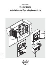
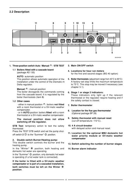
2.2 Description<br />
2 allures<br />
1. Three-position switch Auto / Manual / STB TEST<br />
1.1 Boilers fitted with a cascade board<br />
(package AD 135)<br />
11 8 9 1 10 13 6<br />
AUTO: automatic position<br />
This position allows automatic operation of the<br />
installation under the control of the Diematic-m<br />
Delta regulator.<br />
Manual : manual position<br />
The boiler disregards the commands coming<br />
from the cascade board. It is regulated by the<br />
boiler thermostats (item 5)<br />
1.2 Other cases<br />
- either in manual position : boilers not fitted<br />
with a room thermostat or a SV-matic weather<br />
compensator.<br />
- or in AUTO position: boilers fitted with a room<br />
thermostat or a SV-matic weather compensator.<br />
The manual position does not allow<br />
switching off the regulator.<br />
STB Test: temporary action to test the safety<br />
thermostat:<br />
Press the TEST STB switch and set the pump shutoff<br />
switch 2 to the "Summer" position.<br />
2. Double switch Burner/Heating pump:<br />
This double switch controls the burner and the<br />
heating pump.<br />
In the "Winter" position, both heating and<br />
domestic hot water are operating.<br />
In the "Summer" position, only domestic hot water<br />
is operating (if a hot water tank is connected).<br />
If the boiler is fitted with a SV-matic weather<br />
compensator or is part of a cascaded installation,<br />
both switches must be left on the Winter<br />
position.<br />
7<br />
30<br />
3<br />
0<br />
l<br />
4<br />
2<br />
6A<br />
14<br />
3. Main ON/OFF switch<br />
4. Locations for hour run meters<br />
for the first and second stages (BG 40 option)<br />
5. Boiler thermostats (adjustment range from 40°C to 90°C):<br />
A factory-set stop limits the maximum temperature<br />
to 75°C. This stop may be moved if necessary (see<br />
chapter 5.1).<br />
6. Stage 1 or stage 2 indicators:<br />
These indicators only light up if the relevant<br />
thermostat or the regulator require heating and if<br />
the safety contact is closed.<br />
7. Boiler thermometer<br />
8. Location for the flue gas thermometer<br />
(Optional package BP 28)<br />
9. Safety thermostat with manual reset<br />
(cut-off temperature: 110°C).<br />
10. 4 A circuit-breaker<br />
with delayed action and manual reset.<br />
11. Location for the optional MB2 domestic hot<br />
water priority module or SV-matic weather<br />
compensator<br />
13. Switch selecting the number of burner stages<br />
14. Burner alarm indicator<br />
5<br />
4<br />
8502N008