K Control panel
K Control panel
K Control panel

You also want an ePaper? Increase the reach of your titles
YUMPU automatically turns print PDFs into web optimized ePapers that Google loves.
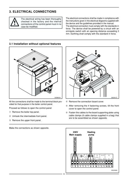
3. ELECTRICAL CONNECTIONS<br />
The electrical wiring has been thoroughly<br />
checked in the factory and the internal<br />
connections of the control <strong>panel</strong> must in no<br />
case be modified.<br />
3.1 Installation without optional features<br />
All the connections shall be made to the terminal block provided<br />
for that purpose in the boiler control <strong>panel</strong>.<br />
Proceed as follows to open the control <strong>panel</strong>:<br />
➀ Remove the boiler top <strong>panel</strong>.<br />
➁ Unhook the intermediate front <strong>panel</strong>.<br />
➂ Remove the upper front <strong>panel</strong>.<br />
Make the connections as shown opposite.<br />
1<br />
7<br />
8<br />
6<br />
9<br />
5<br />
4<br />
3<br />
7<br />
8<br />
6<br />
9<br />
5<br />
4<br />
3<br />
2<br />
3<br />
8358N024<br />
6<br />
The electrical connections shall be made in compliance with<br />
the instructions given in the electrical diagrams supplied with<br />
the device and the guidelines provided in the manual.<br />
The electrical connection must comply with the standards in<br />
force. The device shall be powered by a circuit with an<br />
omnipole switch with an opening distance exceeding 3<br />
mm. Earthing shall comply with the standard in force.<br />
POMPE DE RECYCLAGE<br />
KESSELKREISPUMPE<br />
SHUNT PUMP<br />
1 2 3 4 5 6 7 8 9 10 11 12 13 14 15 16<br />
L N L N L N L N L N<br />
ALI<br />
CS VA - TS VS<br />
230V 50Hz<br />
ALIMENTATION<br />
STROMZUFÜHR<br />
MAIN SUPPLY<br />
6<br />
VOYANT ALARME TS<br />
TS ALARMLEUCHTE<br />
TS ALARM INDICATOR<br />
SAFETY CONTACT<br />
VOYANT ALARME TS<br />
TS ALARMLEUCHTE<br />
TS ALARM INDICATOR<br />
VANNE DE SECURITE<br />
SICHERHEITSVENTIL<br />
SAFETY VALVE<br />
CONTACT DE SECURITE<br />
SICHERHEITSKONTACT<br />
➃ Remove the connection board cover.<br />
➄ After removing the 4 fastening screws, tilt the front<br />
cover to open the control <strong>panel</strong>.<br />
➅ Fasten the cables to the board supporting plate using<br />
cable clamps (6 cable clamps supplied in a bag) that<br />
are to be assembled as shown opposite.<br />
230V<br />
Main supply<br />
3x 0,75 mm 2 mini.<br />
Heating<br />
pump<br />
3x 0,75 mm 2 mini.<br />
230V 50Hz<br />
ALI<br />
CS VA-TS VS<br />
L N L N L N<br />
L N L N<br />
1 2 3 4 5 6 7 8 9 10 11 12 13 14 15 16<br />
4<br />
5<br />
8502N127<br />
8502N086