K Control panel
K Control panel
K Control panel

You also want an ePaper? Increase the reach of your titles
YUMPU automatically turns print PDFs into web optimized ePapers that Google loves.
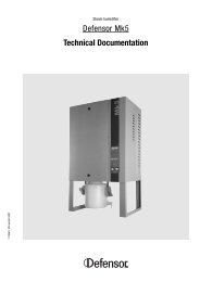
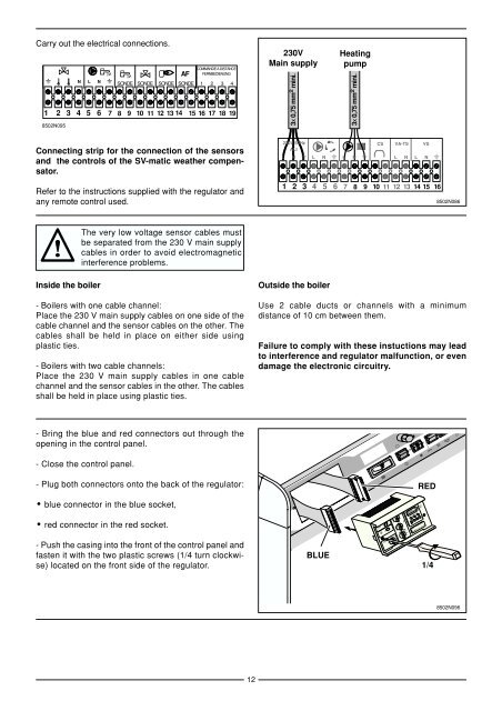
Carry out the electrical connections.<br />
N L N<br />
AF<br />
SONDE SONDE SONDE SONDE<br />
COMMANDE A DISTANCE<br />
FERNBEDIENUNG<br />
1 2 3 4<br />
1 2 3 4 5 6 7 8 9 10 11 12 13 14 15 16 17 18 19<br />
8502N095<br />
Connecting strip for the connection of the sensors<br />
and the controls of the SV-matic weather compensator.<br />
Refer to the instructions supplied with the regulator and<br />
any remote control used.<br />
Inside the boiler<br />
The very low voltage sensor cables must<br />
be separated from the 230 V main supply<br />
cables in order to avoid electromagnetic<br />
interference problems.<br />
- Boilers with one cable channel:<br />
Place the 230 V main supply cables on one side of the<br />
cable channel and the sensor cables on the other. The<br />
cables shall be held in place on either side using<br />
plastic ties.<br />
- Boilers with two cable channels:<br />
Place the 230 V main supply cables in one cable<br />
channel and the sensor cables in the other. The cables<br />
shall be held in place using plastic ties.<br />
- Bring the blue and red connectors out through the<br />
opening in the control <strong>panel</strong>.<br />
- Close the control <strong>panel</strong>.<br />
- Plug both connectors onto the back of the regulator:<br />
● blue connector in the blue socket,<br />
● red connector in the red socket.<br />
- Push the casing into the front of the control <strong>panel</strong> and<br />
fasten it with the two plastic screws (1/4 turn clockwise)<br />
located on the front side of the regulator.<br />
12<br />
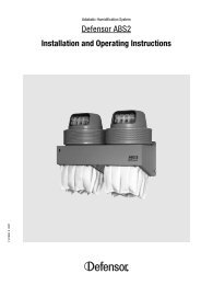
230V<br />
Main supply<br />
3x 0,75 mm 2 mini.<br />
Outside the boiler<br />
3x 0,75 mm 2 mini.<br />
230V 50Hz<br />
ALI<br />
CS VA-TS VS<br />
L N L N L N<br />
L N L N<br />
1 2 3 4 5 6 7 8 9 10 11 12 13 14 15 16<br />
8502N086<br />
Use 2 cable ducts or channels with a minimum<br />
distance of 10 cm between them.<br />
Failure to comply with these instuctions may lead<br />
to interference and regulator malfunction, or even<br />
damage the electronic circuitry.<br />
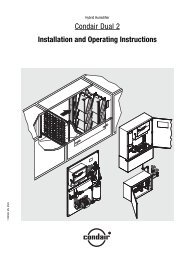
BLUE<br />
Heating<br />
pump<br />
2,5<br />
1,0<br />
3<br />
0,5<br />
3,5<br />
1,5 2<br />
2,5<br />
1,0<br />
3<br />
0,5<br />
3,5<br />
14 26<br />
20<br />
14<br />
50<br />
40<br />
60<br />
30<br />
20 80<br />
8<br />
1 2 3 4 5 6 7<br />
1...7 - +<br />
Prog<br />
RED<br />
331 DB<br />
1/4<br />
8502N096