Engineering System - Siemens Automation and Drives Group
Engineering System - Siemens Automation and Drives Group
Engineering System - Siemens Automation and Drives Group

You also want an ePaper? Increase the reach of your titles
YUMPU automatically turns print PDFs into web optimized ePapers that Google loves.
■ Overview<br />
The SIGUARD safety system is based on special terminal <strong>and</strong><br />
power modules that can be combined with the ET 200S motor<br />
starters <strong>and</strong> a failsafe kit to achieve the highest safety category<br />
4 (according to EN 954-1). It enables the evaluation of emergency<br />
stop circuits, the monitoring of protective doors or the implementation<br />
of time-delayed shut-downs. The costs involved in<br />
the configuration <strong>and</strong> wiring of conventional safety systems are<br />
no longer incurred. All st<strong>and</strong>ard safety applications can be covered<br />
with SIGUARD (see the ET 200S manual for examples of<br />
applications).<br />
■ Design<br />
Terminal modules for SIGUARD power modules<br />
The terminal modules integrate the SIGUARD power modules.<br />
Using different terminal modules it is possible to separate various<br />
safety circuits by function or cascade them. Each group of<br />
this type has to be terminated with a SIGUARD PM-X connection<br />
module.<br />
The TM-PF30 S47-B1 terminal module always st<strong>and</strong>s at the<br />
beginning of a safety segment <strong>and</strong> integrates either the PM-<br />
DF1 power module for emergency stop applications or the<br />
PM-DF2 power module for protective door monitoring. The 2channel<br />
connection of the safety sensor (e.g. emergency stop<br />
sensor) as well as the 24-V supplies for the electronics (U1 )<br />
<strong>and</strong> the contactors (U2 ) of the motor starters have to be connected<br />
to this terminal module. Connections for the ON button<br />
(enable) <strong>and</strong> the safe output of the power module are also<br />
available.<br />
The TM-PF30 S47-B0 terminal module is used for the cascading<br />
of subordinate safety segments <strong>and</strong> integrates either the<br />
PM-D F1 power module for emergency stop applications or<br />
the PM-D F2 power module for protective door monitoring. No<br />
additional auxiliary voltage has to be connected to this terminal<br />
module. The supply is fed through the terminal module<br />
voltage buses from the preceding PM-D F1 or PM-D F2 power<br />
module. Switching off the voltage of the preceding power<br />
module means that the terminal module has no voltage either.<br />
The TM-PF30 S47-C1 terminal module always st<strong>and</strong>s at the<br />
beginning of an expansion of a safety segment in a new station,<br />
e.g. in an interlaced configuration. It integrates the PM-D<br />
F3 power module for time-delayed shut-down or the PM-D F4<br />
power module for direct shut-down in physically separated<br />
ET 200S stations. The 24 V supplies for the electronics (U1)<br />
<strong>and</strong> for the contactors (U2) are fed in anew. The shut-down<br />
comm<strong>and</strong> of a preceding ET 200S station is integrated<br />
through a safe input. Separate terminals are available for connecting<br />
the feedback circuit to the upstream ET 200S station.<br />
It is not possible to connect safety sensors to this terminal<br />
module.<br />
The TM-PF30 S47-C0 terminal module is used for the cascading<br />
of subordinate safety segments <strong>and</strong> integrates either the<br />
PM-D F3 power module for time-delayed shut-down or the PM-<br />
D F4 power module. Only the U2 supply voltage has to be connected<br />
to this terminal module. The U1 supply is fed through<br />
the terminal module voltage buses of the preceding power<br />
module (voltage group section). It is not possible to connect<br />
safety sensors to this terminal module.<br />
The TM-PF30 S47-D0 terminal module is used to integrated<br />
the PM-D F5 power module. At this terminal module it is possible<br />
to forward safe signals to external systems through four<br />
groups, each with two safety relay contacts in redundant configuration.<br />
The terminal module must always be positioned between<br />
one of the afore-mentioned terminal modules <strong>and</strong> a terminal<br />
module for the TM-X connection module. It is not<br />
possible to connect safety sensors to this terminal module<br />
Process I/O<br />
ET 200S distributed I/O<br />
SIGUARD safety engineering<br />
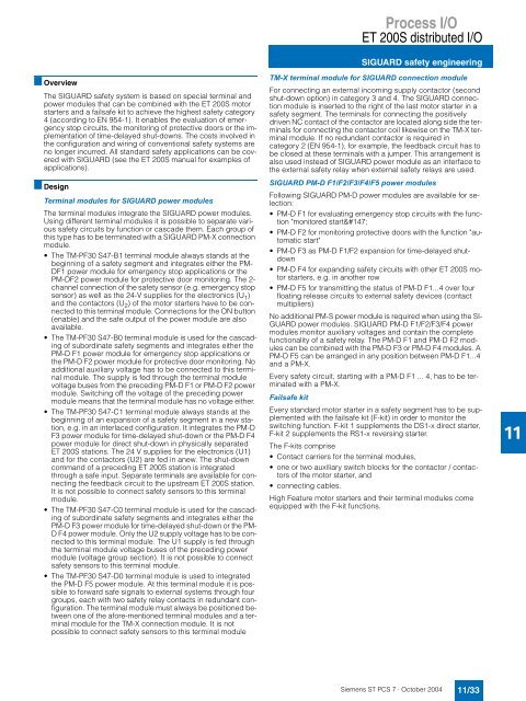
TM-X terminal module for SIGUARD connection module<br />
For connecting an external incoming supply contactor (second<br />
shut-down option) in category 3 <strong>and</strong> 4. The SIGUARD connection<br />
module is inserted to the right of the last motor starter in a<br />
safety segment. The terminals for connecting the positively<br />
driven NC contact of the contactor are located along side the terminals<br />
for connecting the contactor coil likewise on the TM-X terminal<br />
module. If no redundant contactor is required in<br />
category 2 (EN 954-1), for example, the feedback circuit has to<br />
be closed at these terminals with a jumper. This arrangement is<br />
also used instead of SIGUARD power module as an interface to<br />
the external safety relay when external safety relays are used.<br />
SIGUARD PM-D F1/F2/F3/F4/F5 power modules<br />
Following SIGUARD PM-D power modules are available for selection:<br />
PM-D F1 for evaluating emergency stop circuits with the function<br />
"monitored start“<br />
PM-D F2 for monitoring protective doors with the function "automatic<br />
start"<br />
PM-D F3 as PM-D F1/F2 expansion for time-delayed shutdown<br />
PM-D F4 for exp<strong>and</strong>ing safety circuits with other ET 200S motor<br />
starters, e.g. in another row<br />
PM-D F5 for transmitting the status of PM-D F1...4 over four<br />
floating release circuits to external safety devices (contact<br />
multipliers)<br />
No additional PM-S power module is required when using the SI-<br />
GUARD power modules. SIGUARD PM-D F1/F2/F3/F4 power<br />
modules monitor auxiliary voltages <strong>and</strong> contain the complete<br />
functionality of a safety relay. The PM-D F1 <strong>and</strong> PM-D F2 modules<br />
can be combined with the PM-D F3 or PM-D F4 modules. A<br />
PM-D F5 can be arranged in any position between PM-D F1...4<br />
<strong>and</strong> a PM-X.<br />
Every safety circuit, starting with a PM-D F1 ... 4, has to be terminated<br />
with a PM-X.<br />
Failsafe kit<br />
Every st<strong>and</strong>ard motor starter in a safety segment has to be supplemented<br />
with the failsafe kit (F-kit) in order to monitor the<br />
switching function. F-kit 1 supplements the DS1-x direct starter,<br />
F-kit 2 supplements the RS1-x reversing starter.<br />
The F-kits comprise<br />
Contact carriers for the terminal modules,<br />
one or two auxiliary switch blocks for the contactor / contactors<br />
of the motor starter, <strong>and</strong><br />
connecting cables.<br />
High Feature motor starters <strong>and</strong> their terminal modules come<br />
equipped with the F-kit functions.<br />
<strong>Siemens</strong> ST PCS 7 · October 2004<br />
11/33<br />
11