
You also want an ePaper? Increase the reach of your titles
YUMPU automatically turns print PDFs into web optimized ePapers that Google loves.
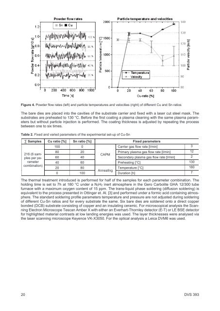
Figure 4. Powder flow rates (left) and particle temperatures and velocities (right) of different Cu and Sn ratios<br />
The bare dies are placed into the cavities of the substrate carrier and fixed with a laser cut steel mask. The<br />
substrates are preheated to 130 °C. Before the first coating a plasma cleaning with the same plasma parameters<br />
but without particle injection is performed. The coating thickness is adjusted by repeating the process<br />
between one to six times.<br />
Table 2. Fixed and varied parameters of the experimental set-up of Cu-Sn<br />
∑ Samples Cu ratio [%] Sn ratio [%] Fixed parameters<br />
216 (6 samples<br />
per parameter<br />
combination)<br />
100 0<br />
Carrier gas flow rate [l/min] 3<br />
80 20 Primary plasma gas flow rate [l/min] 12<br />
CAPM<br />
60 40 Secondary plasma gas flow rate [l/min] 2<br />
40 60 Preheating [°C] 130<br />
20 80<br />
Temperature [°C] 180<br />
Annealing<br />
0 100 Duration [h] 7<br />
The thermal treatment introduced is performed for half of the samples for each parameter combination. The<br />
holding time is set to 7h at 180 °C under a N2H2 inert atmosphere in the Gero Carbolite GHA 12/300 tube<br />
furnace with a maximum oxygen content of 15 ppm. The trans-liquid phase soldering (diffusion soldering) is<br />
equivalent to the process presented in Ottinger et. Al. [3] and performed under a formic acid containing atmosphere.<br />
The standard soldering profile parameters temperature and pressure are not adjusted during soldering<br />
of different Cu-Sn ratios and for every substrate the same. Six bare dies are soldered onto a direct copper<br />
bonded (DCB) substrate consisting of copper and an insulating ceramic. For microscopical analysis the Scanning<br />
Electron Microscope Tescan Amber X with either an Everhart-Thornley detector (E-T) or LE BSE detector<br />
for highlighted material contrasts at low landing energies was used. The layer thicknesses were analysed via<br />
the laser scanning microscope Keyence VK-X3050. For the optical analysis a Leica DVM6 was used.<br />
20<br />
<strong>DVS</strong> 393