Power Vented Gas Models FPSH/FPCR/FPST with ... - Geisel
Power Vented Gas Models FPSH/FPCR/FPST with ... - Geisel
Power Vented Gas Models FPSH/FPCR/FPST with ... - Geisel
Create successful ePaper yourself
Turn your PDF publications into a flip-book with our unique Google optimized e-Paper software.
F. Joint assembly<br />
Working quickly, insert the pipe into the fitting socket bottom<br />
and give the pipe or fitting a 1/4" turn to evenly distribute the<br />
cement. Do not continue to rotate the pipe after it has hit the<br />
bottom of the fitting socket. A good joint will have sufficient<br />
cement to make a bead all the way around the outside of the<br />
fitting hub. The fitting will have a tendency to slide back while<br />
the cement is still wet so hold the joint together for about 15<br />
seconds.<br />
STEP G<br />
G. Cleanup and joint movement<br />
Remove all excess cement from around the pipe and fitting<br />
<strong>with</strong> a dry cotton rag. This must be done while the cement is<br />
still soft.<br />
The joint should not be disturbed immediately after the<br />
cementing procedure, and sufficient time should be allowed<br />
for proper curing of the joint. Exact drying time is difficult to<br />
predict because it depends on variables such as temperature,<br />
humidity and cement integrity. For more specific information,<br />
you should contact your solvent cement manufacturer.<br />
T & P VALVE and PIPE INSULATION (On Selected <strong>Models</strong>)<br />
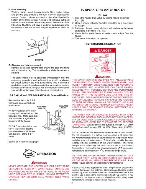
Remove insulation for T & P<br />
Valve and pipe connections<br />
from carton.<br />
Fit pipe insulation over the incoming<br />
cold water line and the<br />
hot water line. Make sure that<br />
the insulation is against the<br />
top cover of the heater.<br />
Fit T & P valve insulation over<br />
valve. Make sure that the<br />
insulation does not interfere<br />
<strong>with</strong> the lever of the T & P<br />
valve.<br />
Secure all insulation using tape.<br />
OPERATION<br />
WARNING<br />
NEVER OPERATE THE HEATER WITHOUT FIRST BEING<br />
CERTAIN IT IS FILLED WITH WATER AND A TEMPERATURE<br />
AND PRESSURE RELIEF VALVE IS INSTALLED IN THE RELIEF<br />
VALVE OPENING OF THE HEATER. DO NOT ATTEMPT TO<br />
OPERATE HEATER WITH COLD WATER INLET VALVE<br />
CLOSED.<br />
12<br />
TO OPERATE THE WATER HEATER<br />
FILLING<br />
1. Close the heater drain valve by turning handle clockwise .<br />
Fig. 1 (T)<br />
2. Open a nearby hot water faucet to permit the air in the system<br />
to escape.<br />
3. Fully open the cold water inlet pipe valve (allowing the heater<br />
and piping to be filled. Fig. 1(M)<br />
4. Close the hot water faucet as water starts to flow from the<br />
faucet.<br />
5. The heater is ready to be operated.<br />
TEMPERATURE REGULATION<br />
WARNING<br />
THIS WATER HEATER IS EQUIPPED WITH AN ADJUSTABLE<br />
THERMOSTAT TO CONTROL WATER TEMPERATURE. HOT<br />
WATER TEMPERATURES REQUIRED FOR AUTOMATIC<br />
DISHWASHER AND LAUNDRY USE CAN CAUSE PAINFUL<br />
SCALDING WITH POSSIBLE SERIOUS AND PERMANENT<br />
INJURY. THE TEMPERATURE AT WHICH INJURY OCCURS<br />
VARIES WITH THE PERSON'S AGE AND THE TIME OF<br />
EXPOSURE. THE SLOWER RESPONSE TIME OF CHILDREN,<br />
AGED OR DISABLED PERSONS INCREASES THE HAZARDS<br />
TO THEM. NEVER ALLOW SMALL CHILDREN TO USE A HOT<br />
WATER TAP OR TO DRAW THEIR OWN BATH WATER. NEVER<br />
LEAVE A CHILD OR DISABLED PERSON UNATTENDED IN A<br />
BATHTUB OR SHOWER.<br />
THE WATER HEATER SHOULD BE LOCATED IN AN AREA<br />
WHERE THE GENERAL PUBLIC DOES NOT HAVE ACCESS.<br />
IF A SUITABLE AREA IS NOT AVAILABLE, A COVER SHOULD<br />
BE INSTALLED OVER THE THERMOSTAT TO PREVENT<br />
TAMPERING. Suitable covers are available through A.O. Smith<br />
Water Products Company, 5621 W. 115th Street, Alsip, IL 60803.<br />
It is recommended that lower water temperatures be used to avoid<br />
the risk of scalding. It is further recommended, in all cases, that<br />
the water temperature dial be set for the lowest temperature which<br />
satisfies your hot water needs. This will also provide the most<br />
energy efficient operation of the water heater. The water<br />
temperature adjusting dial was factory set at the lowest<br />
temperature; Turning the dial counterclockwise decreases<br />
temperature, and clockwise increases temperature.<br />
SETTING THE WATER HEATER TEMPERATURE AT 120°F<br />
(APPROX. "HOT" MARK ON TEMPERATURE SETTING DIAL<br />
OF GAS VALVE) WILL REDUCE THE RISK OF SCALDS. Some<br />
states require settings at specific lower temperatures.<br />
Figure 9 shows the approximate water temperatures produced at<br />
various thermostat dial settings. Short repeated heating cycles<br />
caused by small hot water uses can cause temperatures at the<br />
point of use to exceed the thermostat setting by up to 30°F. If you<br />
experience this type of use you should consider using lower<br />
temperature settings to reduce scald hazards.


