Power Vented Gas Models FPSH/FPCR/FPST with ... - Geisel
Power Vented Gas Models FPSH/FPCR/FPST with ... - Geisel
Power Vented Gas Models FPSH/FPCR/FPST with ... - Geisel

You also want an ePaper? Increase the reach of your titles
YUMPU automatically turns print PDFs into web optimized ePapers that Google loves.
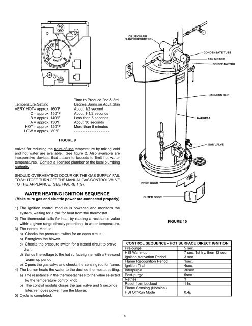
Time to Produce 2nd & 3rd<br />
Temperature Setting Degree Burns on Adult Skin<br />
VERY HOT= approx. 160*F About 1/2 second<br />
C = approx. 150*F About 1-1/2 seconds<br />
B = approx. 140*F Less than 5 seconds<br />
A = approx. 130*F About 30 seconds<br />
HOT = approx. 120*F More than 5 minutes<br />
LOW = approx. 80*F - - - - - - - - - - - - - - - -<br />
FIGURE 9<br />
Valves for reducing the point-of-use temperature by mixing cold<br />
and hot water are available. See figure 2. Also available are<br />
inexpensive devices that attach to faucets to limit hot water<br />
temperatures. Contact a licensed plumber or the local plumbing<br />
authority.<br />
SHOULD OVERHEATING OCCUR OR THE GAS SUPPLY FAIL<br />
TO SHUTOFF, TURN OFF THE MANUAL GAS CONTROL VALVE<br />
TO THE APPLIANCE. SEE FIGURE 1(G).<br />
WATER HEATING IGNITION SEQUENCE<br />
(Make sure gas and electric power are connected properly)<br />
1) The ignition control module is powered and monitors the<br />
system, waiting for a call for heat from the thermostat.<br />
2) The thermostat calls for heat by reading a resistance value<br />
<strong>with</strong>in a given range directly proprtional to water temperature.<br />
3) The control Module:<br />
a) Checks the pressure switch for an open circuit.<br />
b) Energizes the blower.<br />
c) Checks the pressure switch for a closed circuit to prove<br />
draft.<br />
d) Sends line voltage to the hot surface igniter <strong>with</strong> a 7-second<br />
warm up period.<br />
e) Opens the gas valve and checks the sensing rod for flame.<br />
4) The burner heats the water to the desired thermostat setting.<br />
a) The resistance in the thermostat rises to the value selected<br />
by the temperature control knob.<br />
b) The control module closes the gas valve and 5 seconds<br />
later, removes power from the blower.<br />
5) Cycle is completed.<br />
14<br />
FIGURE 10<br />
CONTROL SEQUENCE - HOT SURFACE DIRECT IGNITION<br />
Pre-purge 5 sec.<br />
HSI Warm-up 7 sec. 1st try, then 12 sec.<br />
Ignition Activation Period 3 sec.<br />
Flame Recognition Period 1sec.<br />
Ignition Trial 4sec.<br />
Interpurge 30sec.<br />
Post-purge 5sec.<br />
Retries 3<br />
Reset from Lockout 1 hr.<br />
Flame Sensing (Nominal)<br />
HSI Off/Run Mode 0.4µ