Power Vented Gas Models FPSH/FPCR/FPST with ... - Geisel
Power Vented Gas Models FPSH/FPCR/FPST with ... - Geisel
Power Vented Gas Models FPSH/FPCR/FPST with ... - Geisel

You also want an ePaper? Increase the reach of your titles
YUMPU automatically turns print PDFs into web optimized ePapers that Google loves.
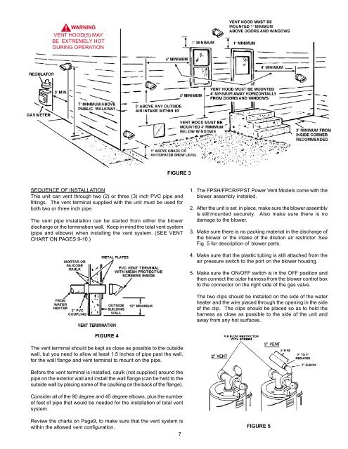
WARNING<br />
VENT HOOD(S) MAY<br />
BE EXTREMELY HOT<br />
DURING OPERATION<br />
SEQUENCE OF INSTALLATION<br />
This unit can vent through two (2) or three (3) inch PVC pipe and<br />
fittings. The vent terminal supplied <strong>with</strong> the unit must be used for<br />
both two or three inch pipe.<br />
The vent pipe installation can be started from either the blower<br />
discharge or the termination wall. Keep in mind the total vent system<br />
(pipe and elbows) when installing the vent system. (SEE VENT<br />
CHART ON PAGES 9-10.)<br />
FIGURE 4<br />
FIGURE 3<br />
The vent terminal should be kept as close as possible to the outside<br />
wall, but you need to allow at least 1.5 inches of pipe past the wall,<br />
for the wall flange and vent terminal to mount on the pipe.<br />
Before the vent terminal is installed, caulk (not supplied) around the<br />
pipe on the exterior wall and install the wall flange (can be held to the<br />
outside wall by placing some of the caulking on the back of the flange).<br />
Consider all of the 90 degree and 45 degree elbows, plus the number<br />
of feet of pipe that would be needed for the installation of total vent<br />
system.<br />
Review the charts on Page9, to make sure that the vent system is<br />
<strong>with</strong>in the allowed vent configuration.<br />
7<br />
1. The <strong>FPSH</strong>/<strong>FPCR</strong>/<strong>FPST</strong> <strong>Power</strong> Vent <strong>Models</strong> come <strong>with</strong> the<br />
blower assembly installed.<br />
2. After the unit is set in place, make sure the blower assembly<br />
is still mounted securely. Also make sure there is no<br />
damage to the blower.<br />
3. Make sure there is no packing material in the discharge of<br />
the blower or the intake of the dilution air restrictor. See<br />
Fig. 5 for description of blower parts.<br />
4. Make sure that the plastic tubing is still attached from the<br />
air pressure switch to the port on the blower housing.<br />
5. Make sure the ON/OFF switch is in the OFF position and<br />
then connect the outer harness from the blower control box<br />
to the connector on the right side of the gas valve.<br />
The two clips should be installed on the side of the water<br />
heater and the wire placed through the opening in the side<br />
of the clip. The clips should be placed so as to hold the<br />
harness as close as possible to the side of the unit and<br />
away from any hot surfaces.<br />
FIGURE 5