Power Vented Gas Models FPSH/FPCR/FPST with ... - Geisel
Power Vented Gas Models FPSH/FPCR/FPST with ... - Geisel
Power Vented Gas Models FPSH/FPCR/FPST with ... - Geisel

You also want an ePaper? Increase the reach of your titles
YUMPU automatically turns print PDFs into web optimized ePapers that Google loves.
THIS UNIT IS MANUFACTURED WITH AN EXTERNAL<br />
CONTROL HARNESS FOR EASIER REPLACEMENT IF THE<br />
HARNESS OR CONNECTORS GET DAMAGED.<br />
6. Do not plug in power cord until vent system is completely<br />
installed. The <strong>Power</strong> Vent operates on 110-120 Vac, therefore<br />
a grounded outlet must be <strong>with</strong>in reach of the six (6) foot flexible<br />
power cord supplied <strong>with</strong> the unit (see fig. 1). The power cord<br />
supplied may be used only where local codes permit. If local<br />
codes do not permit the use of a flexible power supply cord:<br />
a.)Make sure the unit is unplugged from wall outlet. Remove<br />
screw and open access panel on side of control box.<br />
b.) Cut the flexible power cord, leaving enough to be able<br />
to make connections, then remove the strain relief fitting<br />
from box.<br />
c.) Install suitable conduit fitting in top of enclosure and<br />
then follow (D) and (E) below.<br />
d.) Splice field wiring into existing wiring using code authorized<br />
method (wire nuts, etc.).<br />
e.) Be certain that neutral and line connections are not reversed<br />
when making these connections.<br />
f.) Close panel on the side of control box, make sure that access<br />
panel issecured shut.<br />
CAUTION<br />
LABEL ALL WIRES PRIOR TO DISCONNECTION WHEN<br />
SERVICING CONTROLS. WIRING ERRORS CAN CAUSE<br />
IMPROPER AND DANGEROUS OPERATION. VERIFY PROPER<br />
OPERATION AFTER SERVICING.<br />
FIGURE 6<br />
8<br />
INSTALLATION OF VENT SYSTEM<br />
(Refer to Figures 3, 4, 5,7 and 8 as guides).<br />
1. Plan the route of the vent system from the discharge of the<br />
blower to the planned location of the vent terminal. Layout the<br />
total vent system to use minimum of vent pipe and elbows.<br />
2. Refer to charts on page 9, for instructions for total vent length,<br />
for both two (2) and three (3) inch vent pipe. See information<br />
below on what types of material can be used for pipe and<br />
fittings. Note: Use only vent terminal supplied <strong>with</strong> unit!<br />
3. See the instructions on pages 11 and 12 for the proper method<br />
of cutting and cementing the PVC pipe and fittings.<br />
4. A 2” elbow or coupling should be mounted to the discharge or<br />
the blower and secured <strong>with</strong> silicone sealant.<br />
NOTE: This unit can be vented using only PVC (Class<br />
160,ASTM D-2241; Schedule 40,ASTM D-1785; or Cellular<br />
Core Schedule 40 DWV,ASTM F-891), Schedule 40<br />
CPVC(ASTM F-441), or ABS(ASTM D-2661) pipe. The fittings,<br />
other than the TERMINATION, should be equivalent to PVC-<br />
DWV fittings meeting ASTM D-2665 (Use CPVC fittings, ASTM<br />
F-438 for CPVC pipe and ABS fittings, ASTM D-2661/3311 for<br />
ABS pipe. If CPVC or ABS pipe and fittings are used, then the<br />
proper cement must be used for all joints, including joining the<br />
pipe to the Termination Tee (PVC Material).<br />
PVC Materials should use ASTM D-2564 Grade Cement;<br />
CPVC Materials should use ASTM F-493 Grade Cement and;<br />
ABS Materials should use ASTM D-2235 Grade Cement.<br />
NOTE: For Water Heaters in locations <strong>with</strong> high ambient<br />
temperatures (above 100°F) and/or insufficient dilution air, it<br />
is recommended that CPVC or ABS pipe and fittings (MUST<br />
USE SUPPLIED VENT TERMINAL) be used.<br />
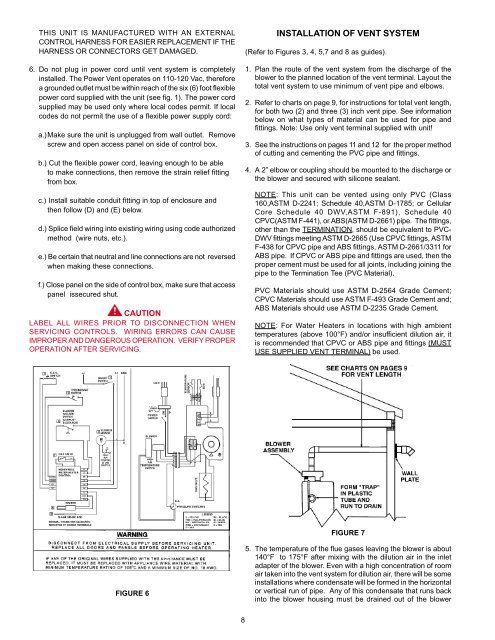
FIGURE 7<br />
5. The temperature of the flue gases leaving the blower is about<br />
140°F to 175°F after mixing <strong>with</strong> the dilution air in the inlet<br />
adapter of the blower. Even <strong>with</strong> a high concentration of room<br />
air taken into the vent system for dilution air, there will be some<br />
installations where condensate will be formed in the horizontal<br />
or vertical run of pipe. Any of this condensate that runs back<br />
into the blower housing must be drained out of the blower