Installer manual - nibe.com
Installer manual - nibe.com
Installer manual - nibe.com

Create successful ePaper yourself
Turn your PDF publications into a flip-book with our unique Google optimized e-Paper software.
16<br />
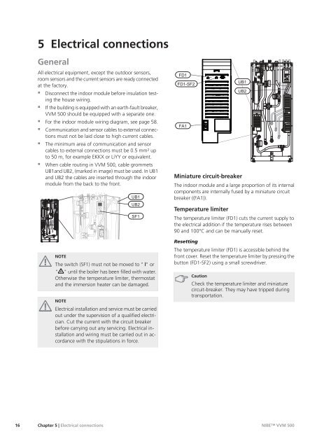
5 Electrical connections<br />
General<br />
All electrical equipment, except the outdoor sensors,<br />
room sensors and the current sensors are ready connected<br />
at the factory.<br />
� Disconnect the indoor module before insulation testing<br />
the house wiring.<br />
� If the building is equipped with an earth-fault breaker,<br />
VVM 500 should be equipped with a separate one.<br />
� For the indoor module wiring diagram, see page 58.<br />
� Communication and sensor cables to external connections<br />
must not be laid close to high current cables.<br />
� The minimum area of <strong>com</strong>munication and sensor<br />
cables to external connections must be 0.5 mm² up<br />
to 50 m, for example EKKX or LiYY or equivalent.<br />
� When cable routing in VVM 500, cable grommets<br />
UB1and UB2, (marked in image) must be used. In UB1<br />
and UB2 the cables are inserted through the indoor<br />
module from the back to the front.<br />
VVM 500<br />
APH<br />
NOTE<br />
B AB<br />
���<br />
���<br />
���<br />
The switch (SF1) must not be moved to " "or<br />
" " until the boiler has been filled with water.<br />
Otherwise the temperature limiter, thermostat<br />
and the immersion heater can be damaged.<br />
NOTE<br />
Electrical installation and service must be carried<br />
out under the supervision of a qualified electrician.<br />
Cut the current with the circuit breaker<br />
before carrying out any servicing. Electrical installation<br />
and wiring must be carried out in accordance<br />
with the stipulations in force.<br />
Chapter 5 | Electrical connections<br />
���<br />
�������<br />
���<br />
���<br />
���<br />
Miniature circuit-breaker<br />
The indoor module and a large proportion of its internal<br />
<strong>com</strong>ponents are internally fused by a miniature circuit<br />
breaker ((FA1)).<br />
Temperature limiter<br />
The temperature limiter (FD1) cuts the current supply to<br />
the electrical addition if the temperature rises between<br />
90 and 100°C and can be <strong>manual</strong>ly reset.<br />
Resetting<br />
The temperature limiter (FD1) is accessible behind the<br />
front cover. Reset the temperature limiter by pressing the<br />
button (FD1-SF2) using a small screwdriver.<br />
Caution<br />
Check the temperature limiter and miniature<br />
circuit-breaker. They may have tripped during<br />
transportation.<br />
VVM 500<br />
NIBE VVM 500<br />
APH