Installer manual - nibe.com
Installer manual - nibe.com
Installer manual - nibe.com

You also want an ePaper? Increase the reach of your titles
YUMPU automatically turns print PDFs into web optimized ePapers that Google loves.
20<br />
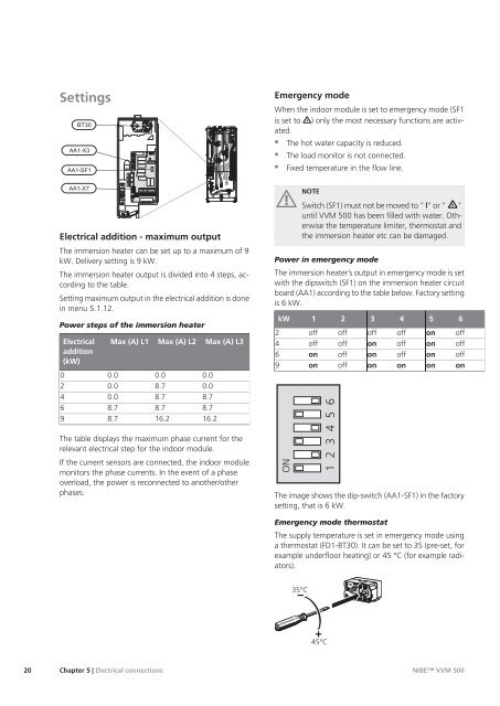
Settings<br />
����<br />
������<br />
�������<br />
������<br />
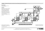
Electrical addition - maximum output<br />
The immersion heater can be set up to a maximum of 9<br />
kW. Delivery setting is 9 kW.<br />
The immersion heater output is divided into 4 steps, according<br />
to the table.<br />
Setting maximum output in the electrical addition is done<br />
in menu 5.1.12.<br />
Power steps of the immersion heater<br />
Electrical<br />
addition<br />
(kW)<br />
0<br />
2<br />
4<br />
6<br />
9<br />
Max (A) L1<br />
0.0<br />
0.0<br />
0.0<br />
8.7<br />
8.7<br />
Max (A) L2<br />
0.0<br />
8.7<br />
8.7<br />
8.7<br />
16.2<br />
Max (A) L3<br />
0.0<br />
0.0<br />
8.7<br />
8.7<br />
16.2<br />
The table displays the maximum phase current for the<br />
relevant electrical step for the indoor module.<br />
If the current sensors are connected, the indoor module<br />
monitors the phase currents. In the event of a phase<br />
overload, the power is reconnected to another/other<br />
phases.<br />
Chapter 5 | Electrical connections<br />
VVM 500<br />
APH<br />
Emergency mode<br />
When the indoor module is set to emergency mode (SF1<br />
is set to ) only the most necessary functions are activated.<br />
� The hot water capacity is reduced.<br />
� The load monitor is not connected.<br />
� Fixed temperature in the flow line.<br />
NOTE<br />
Switch (SF1) must not be moved to " "or" "<br />
until VVM 500 has been filled with water. Otherwise<br />
the temperature limiter, thermostat and<br />
the immersion heater etc can be damaged.<br />
Power in emergency mode<br />
The immersion heater’s output in emergency mode is set<br />
with the dipswitch (SF1) on the immersion heater circuit<br />
board (AA1) according to the table below. Factory setting<br />
is 6 kW.<br />
2<br />
4<br />
6<br />
9<br />
kW<br />
ON<br />
1<br />
off<br />
off<br />
on<br />
on<br />
1 2 3 4 5 6<br />
2<br />
off<br />
off<br />
off<br />
off<br />
3<br />
off<br />
on<br />
on<br />
on<br />
4<br />
off<br />
off<br />
off<br />
on<br />
5<br />
on<br />
on<br />
on<br />
on<br />
6<br />
off<br />
off<br />
off<br />
on<br />
The image shows the dip-switch (AA1-SF1) in the factory<br />
setting, that is 6 kW.<br />
Emergency mode thermostat<br />
The supply temperature is set in emergency mode using<br />
a thermostat (FD1-BT30). It can be set to 35 (pre-set, for<br />
example underfloor heating) or 45 °C (for example radiators).<br />
LEK<br />
NIBE VVM 500