Installer manual - nibe.com
Installer manual - nibe.com
Installer manual - nibe.com

You also want an ePaper? Increase the reach of your titles
YUMPU automatically turns print PDFs into web optimized ePapers that Google loves.
18<br />
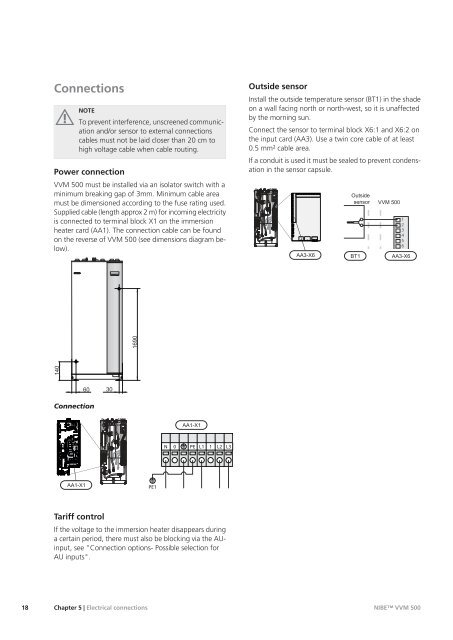
Connections<br />
NOTE<br />
To prevent interference, unscreened <strong>com</strong>munication<br />
and/or sensor to external connections<br />
cables must not be laid closer than 20 cm to<br />
high voltage cable when cable routing.<br />
Power connection<br />
VVM 500 must be installed via an isolator switch with a<br />
minimum breaking gap of 3mm. Minimum cable area<br />
must be dimensioned according to the fuse rating used.<br />
Supplied cable (length approx 2 m) for in<strong>com</strong>ing electricity<br />
is connected to terminal block X1 on the immersion<br />
heater card (AA1). The connection cable can be found<br />
on the reverse of VVM 500 (see dimensions diagram below).<br />
140<br />
Connection<br />
������<br />
60 30<br />
Tariff control<br />
VVM 500<br />
APH<br />
1690<br />
PE1<br />
N<br />
0<br />
������<br />
PE<br />
L1 1 L2 L3<br />
If the voltage to the immersion heater disappears during<br />
a certain period, there must also be blocking via the AUinput,<br />
see "Connection options- Possible selection for<br />
AU inputs".<br />
Chapter 5 | Electrical connections<br />
Outside sensor<br />
Install the outside temperature sensor (BT1) in the shade<br />
on a wall facing north or north-west, so it is unaffected<br />
by the morning sun.<br />
Connect the sensor to terminal block X6:1 and X6:2 on<br />
the input card (AA3). Use a twin core cable of at least<br />
0.5 mm² cable area.<br />
If a conduit is used it must be sealed to prevent condensation<br />
in the sensor capsule.<br />
VVM 500<br />
APH<br />
������<br />
�������<br />
������ ��� ���<br />
���<br />
1<br />
2<br />
3<br />
4<br />
5<br />
6<br />
������<br />
NIBE VVM 500