CLIMATIC™ 50 User manual - Lennox
CLIMATIC™ 50 User manual - Lennox
CLIMATIC™ 50 User manual - Lennox

Create successful ePaper yourself
Turn your PDF publications into a flip-book with our unique Google optimized e-Paper software.
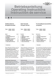
<strong>User</strong> <strong>manual</strong><br />
CLIMATIC <strong>50</strong><br />
ROOFTOP & AIRCOOLAIR<br />
Providing indoor climate comfort<br />
CL<strong>50</strong>-ROOFTOP-IOM-1107-E
Climatic <strong>50</strong><br />
Roof-Top & Aircoolair<br />
INSTALLATION<br />
OPERATING &<br />
MAINTENANCE MANUAL<br />
Ref : CL<strong>50</strong>-RoofTop-IOM-1107-E<br />
LENNOX have been providing environmental solutions since 1895, our range of Baltic TM rooftop continues to meet the<br />
standards that have made LENNOX a household name. Flexible design solutions to meet YOUR needs and uncompromising<br />
attention to detail. Engineered to last, simple to maintain and Quality that becomes a standard. Further Information on<br />
www.lennoxeurope.com.<br />
All the technical and technological information contained in this <strong>manual</strong>, including any drawing and technical descriptions<br />
provided by us, remain the property of <strong>Lennox</strong> and must not be used (except in operation of this product), reproduced,<br />
issued to or made available to third parts without the prior written agreement of <strong>Lennox</strong>.<br />
The technical informations and specifications contained in this <strong>manual</strong> are for reference only. The manufacturer reserves the right to modify<br />
these without warning and without obligation to modify equipment already sold.<br />
CLIMATIC<strong>50</strong> – IOM – Rooftops/ Aircoolair CL<strong>50</strong>-ROOFTOPS-IOM-1107-E 1
TABLE OF CONTENTS<br />
Page<br />
INTRODUCTION 3<br />
CONNECTION 4<br />
CONFIGURATION 8<br />
SCHEDULING – CLOCK SETTING 10<br />
VENTILATION 13<br />
THERMOSTAT / HYGROSTAT – SET POINTS 15<br />
THERMOSTAT / HYGROSTAT – CONTROL PRINCIPLE 17<br />
FRESH AIR DAMPER - FREE-COOLING 18<br />
COMPRESSORS 20<br />
DEFROST – HEAT PUMP 22<br />
SUPPLEMENT OF HEATING (OPTION) 23<br />
CUSTOMIZED INPUT/OUTPUT 25<br />
FAULT CODES<br />
Insufficient airflow 28<br />
Filters Clogged or Missing 29<br />
Ambient Temperature and Humidity, Outside Limits 30<br />
Blowing temperature, outside limits 31<br />
Overheating of Electrical Heating Elements 32<br />
Gas Burner Faults 33<br />
External Humidifier fault 34<br />
Hot Water Circulator Fault 34<br />
Fault in Real Time Clock 35<br />
Extension card fault (BE<strong>50</strong>) 35<br />
Faulty Probes and Sensors 36<br />
Blowing fan 37<br />
Condenser fans 38<br />
Water Condenser Faults 39<br />
Smoke Detector 40<br />
Compressors shut down on LP cut off 41<br />
Compressor shut down onHP cut off or electrical protection 42<br />
COMMUNICATION 43<br />
MASTER/SLAVE 43<br />
BMS 45<br />
CONFIGURING THE BM<strong>50</strong> PLAN ADDRESS 46<br />
ALLOCATION OF DISPLAYS TO THE BM<strong>50</strong> 47<br />
DC<strong>50</strong> COMFORT & DM<strong>50</strong> MULTI CUSTOMER DISPLAY 48<br />
DS<strong>50</strong> SERVICE DISPLAY 53<br />
DS<strong>50</strong> MENU TREE 59<br />
CLIMATIC<strong>50</strong> INPUT/OUTPUT MAPPING 67<br />
MODBUS, LONTALK ADRESS TABLES 70<br />
CLIMATIC<strong>50</strong> – IOM – Rooftops/ Aircoolair CL<strong>50</strong>-ROOFTOPS-IOM-1107-E 2
INTRODUCTION<br />
CLIMATIC<strong>50</strong><br />
The new generation of microprocessor based control, CLIMATICTM <strong>50</strong> may be fitted to the <strong>Lennox</strong> Roof-Top or<br />
AirCooler range. It inherits 20 years of technology and field operating experience from its predecessors the<br />
CLIMATICTM1 and CLIMATICTM 2.<br />
LENNOX has found the latest hardware technology available on the market place and developed a software<br />
specifically designed for Roof-Top and AirCooler applications, maximising the LENNOX units efficiency and<br />
performance.<br />
Compatibility<br />
This documentation is compatible with the programs Roof Top and AirCooler:<br />
• Ranges Baltic, Flexy I, Flexy II, FX and AC, starting from the version 20.0<br />
Warning<br />
Any parameter modification should be carried out by trained and licensed competent technician.<br />
Before start-up or restart of a unit controlled by Climatic <strong>50</strong>, it is mandatory to check adequacy between<br />
Climatic <strong>50</strong> and the unit with its options.<br />
• 38xx menus for unit and options<br />
• 39xx menux for communication<br />
In case of wrong parameters, I/O links could be incorrect and may create some operation problems for<br />
the units and ultimately breakdowns.<br />
<strong>Lennox</strong> cannot be held responsible for any claims on the units due to a wrong parameters sequence or a<br />
parameters modification carried out by non competent technicians. In this case, the warranty will be<br />
legally null and void.<br />
CLIMATIC<strong>50</strong> – IOM – Rooftops/ Aircoolair CL<strong>50</strong>-ROOFTOPS-IOM-1107-E 3
WIRING CONNECTIONS<br />
IMPORTANT WARNING<br />
Any wiring modification on the CLIMATIC <strong>50</strong> must be done by <strong>Lennox</strong> technician or employees having valid<br />
electrical qualification and authorisation.<br />
For any modification of wiring on the 24V supply or on 4-20mA sensor, check the polarity prior to apply<br />
the power. Wrong polarity may cause serious damage and destroy the Plan network. <strong>Lennox</strong> will not<br />
accept liability for damage caused by wrong power connection or any wiring modification done by<br />
people without valid training and qualifications.<br />
Any external connection with the unit, using 24Vac voltage should not exceed a length of more than 30m.<br />
It concerns external contacts connected to Climatic<strong>50</strong> logical inputs or humidifier control connection<br />
to the output 0-10v.<br />
Over 30 m, the installer must interface this information with relays or converters.<br />
In any case, the 24Vac control voltage must not be used to drive external function with Climatic<strong>50</strong><br />
logical output<br />
WARNING: Separate as much as possible probes, displays, logical input cables from power cables with strong inductive load, in<br />
order to avoid possible electromagnetic perturbations<br />
.<br />
CONNECTION<br />
SENSORS AND PROBES<br />
External sensors or probes connection must be carried out with the following cable:<br />
- Cable length up to 20m: AWG22 (0.34 mm ²), 1 pair crossed with screen (2 pairs for CO2 sensor).<br />
- Cable length up to <strong>50</strong>m: LiYCY-P (0.34 mm ²), 1 pair with general shield. (2 pairs for CO2 sensor).<br />
The cable length should not exceed <strong>50</strong>m.<br />
For a better electromagnetic protection, <strong>Lennox</strong> recommends the use of LiYCY-P cable<br />
ROOM TEMPERATURE PROBE (NTC)<br />
The room temperature probe (- BT10) is connected to the Climatic main board BM<strong>50</strong> <strong>50</strong> entry B7 connector J6 (refer to the unit<br />
electrical wiring diagram).<br />
ROOM HUMIDITY SENSOR (0-20mA/Option)<br />
The room humidity sensor (- BH10) is connected to the Climatic extension board BE<strong>50</strong> entry B1 connector J9 (refer to the unit<br />
electrical wiring diagram).<br />
ROOM AIR QUALITY SENSOR CO² (4-20mA / Option)<br />
The room air quality sensor (-BG10) is connected to Climatic main board BM<strong>50</strong> entry B2 connector (refer to the unit electrical<br />
wiring diagram).<br />
DISPLAY DS<strong>50</strong><br />
The Display DS<strong>50</strong> can be connected to the Climatic either on one of the RJ12 connectors located on the board DT<strong>50</strong>, or<br />
directly on the main board BM<strong>50</strong> connector J10.<br />
Connection is carried out by the flat 1.5m cable delivered with this DS<strong>50</strong>.<br />
In any the case, Display DS<strong>50</strong> cannot be remotely connected.<br />
In case of Master/Slave installation, one, and only one, display DS<strong>50</strong> must be connected on the pLan bus.<br />
DISPLAY DC<strong>50</strong> or DM<strong>50</strong> (Remote CONNECTION)<br />
Warning:<br />
A wrong wiring of the display immediately damage it and/or the main board BM<strong>50</strong>.<br />
The optional DC<strong>50</strong>/DM<strong>50</strong> is designed to be mounted on the wall.<br />
Fit the cable from the DT<strong>50</strong> board through the back piece<br />
Fasten the back piece to the wall using the rounded head screws supplied in the packaging<br />
Connect the cable from the main board on the connector on the back of the DC<strong>50</strong> display<br />
Fasten the front panel on the back piece using the flush head screws supplied<br />
Finally fit the click-on frame<br />
CLIMATIC<strong>50</strong> – IOM – Rooftops/ Aircoolair CL<strong>50</strong>-ROOFTOPS-IOM-1107-E 4
Display DC<strong>50</strong> or DM<strong>50</strong> is connected to the Climatic with the DT<strong>50</strong> screw connector.<br />
Connection must be carried out by the following cable:<br />
- Cable length up to 300m: AWG22 (0.34 mm ²), 2 pairs crossed with screen.<br />
- Cable length up to <strong>50</strong>0m: LiYCY-P (0.34 mm ²), 2 pairs with general shield.<br />
The cable length should not exceed <strong>50</strong>0m.<br />
For a better electromagnetic protection, <strong>Lennox</strong> recommends the use of LiYCY-P cable<br />
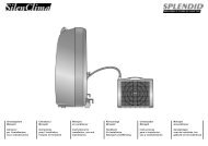
CONNECTION ON DT<strong>50</strong> REPARTITOR<br />
- +<br />
Terminal connection board installation guide DT <strong>50</strong><br />
The board is fitted with three "telephone" RJ12 plugs. Ensure the board is correctly connected.<br />
Standard connection is:<br />
BM<strong>50</strong> on connector C<br />
DC<strong>50</strong>/DM<strong>50</strong> on connector A or SC<br />
DS<strong>50</strong> on connector B<br />
DC<strong>50</strong> / DM<strong>50</strong><br />
3<br />
GND VL<br />
DT<strong>50</strong><br />
Jumpers:<br />
"Displays" are supplied directly by the Climatic board with 30Vdc. Take particular care at the path this 30V is taking when several<br />
boards are being used.<br />
J14 and J15 can switch on or off the direct current from the power supply:<br />
4<br />
2<br />
1<br />
1<br />
2<br />
3<br />
4<br />
CLIMATIC<strong>50</strong> – IOM – Rooftops/ Aircoolair CL<strong>50</strong>-ROOFTOPS-IOM-1107-E 5
J14 and J15 set between1-2 :<br />
Connectors A, B, C and screw connector SC are in parallel. Power is supplied to all connectors.<br />
J14 and J15 set between2-3 :<br />
Connectors B and C are powered in parallel but connector A and screw connector SC are not.<br />
Displays connected to these ports will not be powered.<br />
If J14 and J15 are set in different positions the "terminal connection board" DT<strong>50</strong> DOES NOT WORK and so the<br />
connected displays do not operate.<br />
DM<strong>50</strong> and COMMUNICATION MASTER/SLAVE<br />
The intercard bus (pLan) is connected to Climatic on the J11 connector of board BM<strong>50</strong>.<br />
A star connection is not recommended, for an optimum operation it is advised to connect a maximum of two cables per unit.<br />
Connection must be carried out by the following cable:<br />
- Cable length up to 300m: AWG22 (0.34 mm ²), 2 pairs crossed with screen.<br />
- Cable length up to <strong>50</strong>0m: LiYCY-P (0.34 mm ²), 2 pairs with general shield.<br />
The cable length should not exceed <strong>50</strong>0m.<br />
For a better electromagnetic protection, <strong>Lennox</strong> recommends the use of LiYCY-P cable<br />
Warning:<br />
The power 24Vac of boards BM<strong>50</strong> should not be connected to the earth<br />
CLIMATIC<strong>50</strong> – IOM – Rooftops/ Aircoolair CL<strong>50</strong>-ROOFTOPS-IOM-1107-E 6
BMS COMMUNICATION<br />
The communication bus is connected to Climatic Serial Card daughter board on the BM<strong>50</strong>.<br />
A star connection is not recommended, for an optimum operation it is advised to connect a maximum of two cables per unit.<br />
In case of RS485bus, a resistance of 120Ω 1/4W can be connected on the last unit between the terminals + and -.<br />
Connection must be carried out by the following cable:<br />
- Cable length up to 300m: AWG22 (0.34 mm ²), 2 pairs crossed with screen.<br />
- Cable length up to 1000m: LiYCY-P (0.34 mm ²), 2 pairs with general shield.<br />
The cable length should not exceed 1000m.<br />
For a better electromagnetic protection, <strong>Lennox</strong> recommends the use of LiYCY-P cable<br />
CLIMATIC<strong>50</strong> – IOM – Rooftops/ Aircoolair CL<strong>50</strong>-ROOFTOPS-IOM-1107-E 7
CONFIGURATION<br />
Function<br />
LENNOX© proposes a single software for the whole ranges of Roof-Top and Aircooler.<br />
For a first use, before any operation of the unit, Climatic must be set with parameters in accordance to the range, the size and<br />
the various options of the unit.<br />
Description<br />
The unit configuration is done with following menus (refer also to Menu Tree chapter):<br />
3811 � Unit range choice<br />
[BC] Baltic, cooling only<br />
[BH] Baltic, reversible (heat pump)<br />
[BG] Baltic, gas<br />
[BD] Baltic, gas and reversible (heat pump)<br />
[BGN] Baltic, gas, without compressor<br />
[FC] Flexy 1, cooling only<br />
[FC²] Flexy 2, cooling only<br />
[FH] Flexy 1, reversible (heat pump)<br />
[FH²] Flexy 2, reversible (heat pump)<br />
[FG] Flexy 1, gas<br />
[FG²] Flexy 2, gas<br />
[FD] Flexy 1, gas and reversible (heat pump)<br />
[FD²] Flexy 2, gas and reversible (heat pump)<br />
[FGN] Flexy, gas, without compressor<br />
[FW] Flexy, cool water coil, without compressor<br />
[FX] Roof-Top with module 4 dampers<br />
[ANC] Aircooler, cooling only<br />
[ANH] Aircooler, reversible (heat pump<br />
[NSR] Unit of nonstandard request<br />
3812 � Unit size choice<br />
BC BH BG BD BGN FC FC² FH FH² FG FG² FD FD² FGN FWN FX ANC ANH<br />
BCK020NS BHK020NS BGK020SS BDK020SS BGN001S FCK085N FCM085N FHK085N FHM085N FGK085S FGM085S FDK085S FDM085S FGN002S FWN002S FXK025N ANCM022E ANHM022E<br />
BCK025NS BHK025NS BGK025SS BDK025SS BGN001H FCK100N FCM100N FHK100N FHM100N FGK100S FGM100S FDK100S FDM100S FGN003S FWN003S FXK030N ANCM026E ANHM026E<br />
BCK030NS BHK030NS BGK030SS BDK030SS FCK120N FCM120N FHK120N FHM120N FGK120S FGM120S FDK120S FDM120S FGN004S FWN004S FXK035N ANCM032E ANHM032E<br />
BCK035NS BHK035NS BGK035SS BDK035SS FCK140N FCM1<strong>50</strong>N FHK140N FHM1<strong>50</strong>N FGK140S FGM1<strong>50</strong>S FDK140S FDM1<strong>50</strong>S FGN005S FWN005S FXK040N ANCM038E ANHM038E<br />
BCK040NS BHK040NS BGK040SS BDK040SS FCK160N FCM170N FHK160N FHM170N FGK160S FGM170S FDK160S FDM170S FGN002H FWN002H FXK055N ANCM043E ANHM043E<br />
BCK045NS BHK045NS BGK045SS BDK045SS FCK190N FCM200N FHK190N FHM200N FGK190S FGM200S FDK190S FDM200S FGN003H FWN003H FXK070N ANCM052D ANHM052D<br />
BCK030ND BHK030ND BGK030SD BDK030SD FCM230N FHM230N FGK085H FGM230S FDK085H FDM230S FGN004H FWN004H FXK085N ANCM064D ANHM064D<br />
BCK035ND BHK035ND BGK035SD BDK035SD FGK100H FGM085H FDK100H FDM085H FGN005H FWN005H FXK100N ANCM076D ANHM076D<br />
BCK040ND BHK040ND BGK040SD BDK040SD FGK120H FGM100H FDK120H FDM100H FXK110N ANCM086D ANHM086D<br />
BCK045ND BHK045ND BGK045SD BDK045SD FGK140H FGM120H FDK140H FDM120H FXK140N ANCM112D ANHM112D<br />
BCK0<strong>50</strong>ND BHK0<strong>50</strong>ND BGK0<strong>50</strong>SD BDK0<strong>50</strong>SD FGK160H FGM1<strong>50</strong>H FDK160H FDM1<strong>50</strong>H FXK170N ANCM128D ANHM128D<br />
BCK060ND BHK060ND BGK060SD BDK060SD FGK190H FGM170H FDK190H FDM170H ANCM152D ANHM152D<br />
BCK070ND BHK070ND BGK070SD BDK070SD FGM200H FDM200H<br />
BHK020HS BGK020HS BDK020HS FGM230H FDM230H<br />
BHK025HS BGK025HS BDK025HS<br />
BHK030HS BGK030HS BDK030HS<br />
BHK035HS BGK035HS BDK035HS<br />
BHK040HS BGK040HS BDK040HS<br />
BHK045HS BGK045HS BDK045HS<br />
BHK030HD BGK035HD BDK030HD<br />
BHK035HD BGK040HD BDK035HD<br />
BHK040HD BGK045HD BDK040HD<br />
BHK045HD BGK0<strong>50</strong>HD BDK045HD<br />
BHK0<strong>50</strong>HD BGK060HD BDK0<strong>50</strong>HD<br />
BHK060HD BGK030HD BDK060HD<br />
BHK070HD BGK070HD BDK070HD<br />
3813 � Activation of the Controls humidity option<br />
3814 � Activation of the High Efficiency Main fan and/or Variable speed transmission option,<br />
3815 � Activation of the External Thermostat Temperature Control option,<br />
3821 � Choice of the type of sensor or probe on the refrigeration circuit<br />
[No] No probe or sensor of installed on the circuits<br />
CLIMATIC<strong>50</strong> – IOM – Rooftops/ Aircoolair CL<strong>50</strong>-ROOFTOPS-IOM-1107-E 8
[NTC] Temperature probe `NTC' on the sticks of the coils<br />
[0-5V] Transmitter of pressure `Ratiométrique' on the circuits<br />
[4-20mA] Transmitter of pressure `4-20mA ' on the circuits<br />
3822 � Activation of the Low Ambient Kit option,<br />
3823 � Unit with water condensation<br />
3824 � Activation of the Alternate Defrost option for the Flexy1 range sizes 85 and 100<br />
3831 � Choice of the auxiliary heating type.<br />
[No] No auxillary heating<br />
[Hot W/Coil] Hot water coil<br />
[Gas 2] Gas, 1 slope with 2 steps<br />
[Gas 4] Gas, 2 slopes with 2 steps<br />
[Gas 2 Pro.] Gas, 1 modulating slope<br />
[Gas 4 Pro.] Gas, 2 modulating slope<br />
[ElecH. Ste] Electric heaters, without Triac modulation.<br />
[ElecH. Pro] Electric heaters, with Triac, Positioned after the refrigerant coil<br />
[ElecH. Mix] Electric heaters, with Triac, Positioned before the refrigerant coil<br />
3711 � Choice of the type of gas valves control board.<br />
[BG<strong>50</strong>] Board BG<strong>50</strong><br />
[EF49] Board EF49<br />
[EF48] Board EF48<br />
[EF45] Board EF45<br />
[MMI No] Block gas with output fault in normally open<br />
[MMI Nc] Block gas with output fault in normally closed<br />
3832 � Choice of the type air mixing box<br />
[No] No fresh air<br />
[100%] All fresh air<br />
[0%-100%] Economiser proportional<br />
[0%-<strong>50</strong>%] Economiser proportional, limitation to <strong>50</strong>% of opening<br />
3517 � Activation of the air heat recovery option,<br />
3833 � Choice of the type of air flow sensor<br />
[No] No option<br />
[<strong>50</strong>0pa] Sensor, 0 to <strong>50</strong>0 pa<br />
[1000pa] Sensor, 0 to 1000 pa<br />
3834 � Choice of the air quality sensor<br />
[No] No option<br />
[0-2000] Sensor, 0 to 2000 ppm<br />
[3<strong>50</strong>-2000] Sensor, 3<strong>50</strong> to 2000 ppm (Carel© brand sensor)<br />
CLIMATIC<strong>50</strong> – IOM – Rooftops/ Aircoolair CL<strong>50</strong>-ROOFTOPS-IOM-1107-E 9
SCHEDULING – CLOCK SETTING<br />
CLOCK SETTING<br />
Function<br />
Climatic has a real time clock board, allowing dates and hours functionalities (weekly Program, event recording,…).<br />
Description<br />
Menus 3121 to 3125 give the possibility of setting the internal clock.<br />
The day of the week is calculated by Climatic.<br />
For the countries of the Euro a device allows the automatic swing of the hour summer in hour winter and vice versa. This<br />
functionality can be cancelled by menu 3126.<br />
3121 � Hour.<br />
3122 � Minute.<br />
3123 � Day of the month.<br />
3124 � Month.<br />
3125 � Year.<br />
3126 � Enable automatic switch summer time / winter time.<br />
SCHEDULING<br />
Function<br />
Controlling operation of the unit according to the time and day<br />
Description<br />
CLIMATICTM <strong>50</strong> can handle 4 time zones over the 7 days of the week:<br />
• Zone unoccupied « Night »<br />
• Zone A « Day A »<br />
• Zone B « Day B »<br />
• Zone C « Day C »<br />
•<br />
Starting time (hours and minutes) of each of these zones for each days of the week, can be set using menus 3211 to 3214,<br />
(press ‘Prg’ key to change day).<br />
Each set point integrates the hour and minute’s adjustment, thus a value of 8.3 equal 8.30 a.m.<br />
3211 � Hour, minute of the night starting time (unoccupied)<br />
3212 � Hour, minute of the “day A” starting time<br />
3213 � Hour, minute of the “day B” starting time<br />
3214 � Hour, minute of “day C” starting time<br />
8h00 12h00 13h<strong>50</strong> 20h30 22h00<br />
Monday<br />
Tuesday<br />
Wednesday<br />
Thursday<br />
Friday<br />
Saturday<br />
Sunday<br />
Unoccupied Z :A Z :B Z :C Unoccupied<br />
CLIMATIC<strong>50</strong> – IOM – Rooftops/ Aircoolair CL<strong>50</strong>-ROOFTOPS-IOM-1107-E 10
For each time zone, the set following set points following can be modified:<br />
LIST SET POINT BY ZONE Code<br />
Ambient temperature<br />
DISPLAY<br />
CONFORT<br />
DISPLAY<br />
MAINTENANCE<br />
Set point average 3311 Yes Yes<br />
Set point dynamic 3321 Yes Yes<br />
Cooling Set point 3322 Yes<br />
Heating Set point 3323 Yes<br />
Priority of heating 3324 Yes<br />
Reheating of Fresh Air<br />
Enable 3331 Yes<br />
Priority of heating 3332 Yes<br />
Fresh Air<br />
Set point 3312 Yes<br />
Humidity<br />
Dehumidification 3341 Yes<br />
Humidification 3342 Yes<br />
Authorisation<br />
Free Cooling 3353 Yes<br />
Fresh Air by CO² 3354 Yes<br />
Refrigeration by compressor 3355 Yes<br />
Heating by compressor 3356 Yes<br />
Auxiliary heating 3357 Yes<br />
Humidity Control 3358 Yes<br />
Low noise level 3359 Yes<br />
Other<br />
Fan, Activate 3351 Yes<br />
Fan, Activate, in dead zone 3352 Yes<br />
Minimum fresh air (%) 3353 Yes Yes<br />
Programming<br />
Beginning of zone; each day Yes Yes<br />
Start Uno 3211 Yes Yes<br />
Start z.A 3212 Yes Yes<br />
Start z.B 3213 Yes Yes<br />
Start z.C 3214 Yes Yes<br />
With the DS<strong>50</strong>, for each set point, to press on the key `Prg' to change the periods and to validate the good set point for the good<br />
zone.<br />
Note: “Monday” is considered as the first day of the week for programming the CLIMATIC<strong>50</strong>.<br />
Factory settings:<br />
“Day A” activated from Monday to Saturday 6h�22h<br />
Night mode (unoccupied) for the remaining of time, Sunday included<br />
CLIMATIC<strong>50</strong> – IOM – Rooftops/ Aircoolair CL<strong>50</strong>-ROOFTOPS-IOM-1107-E 11
ANTICIPATION<br />
Function<br />
This allows an anticipated start-up in the morning depending on the outdoor temperature.<br />
Description<br />
This function only works for zone A, and allow the machine to<br />
move from unoccupied zone to zone A earlier if the outdoor<br />
temperature is under a certain value. Use this function to<br />
anticipate the heating start-up during cool days.<br />
This can be adjusted with set point 3221 and 3222.<br />
3221 � bottom of the slope (°C), Anticipation starting point<br />
3222 � Slope in Minutes of anticipation per degrees<br />
7h30<br />
8h00<br />
Example:<br />
Unit with Day A starting at 8.00 am; 3221 set to 3°C and 3222 set to 10 mn/°C;<br />
If the outside temperature is 0°C, then Day A will start at 7.30 a.m.<br />
Hour of starting zone A<br />
0°C 3°C<br />
Air Temp. Outside<br />
CLIMATIC<strong>50</strong> – IOM – Rooftops/ Aircoolair CL<strong>50</strong>-ROOFTOPS-IOM-1107-E 12
VENTILATION<br />
ON / OFF (Start & Stop)<br />
Function<br />
In general, the unit is considered in operation if its supply fan is in operation.<br />
But, according to the set points, the fan may stop in the temperature control dead zone.<br />
Description<br />
To allow the operation of the unit it is necessary that set point 3111 is set to `On' and that the BM<strong>50</strong> logical input ID7 on<br />
the J5 connector is closed.<br />
The 3111 set point adjustment is available on the DC/DM<strong>50</strong> with the ON/OFF functionality.<br />
For each scheduled zone defined in Climatic<strong>50</strong>, it is possible to set the start/stop state. This functionality allows the<br />
unit to stop during a period of time in the day.<br />
When the Room temperature is within the regulation dead zone, for each scheduled zone defined in the Climatic<strong>50</strong> it is<br />
possible run or stop the fan<br />
3111 � Main On/Off.<br />
3351 � On/Off, adjustment by zone.<br />
3352 � On/Off in the temperature control dead zones, adjustment by zone.<br />
STAGGING START<br />
Function<br />
After a power shut-down, you may get the units to restart gradually in order to avoid overloading issues.<br />
Description<br />
The units do not need to be connected; they must simply have different pLan addresses, (see BM<strong>50</strong> pLan address<br />
configuration).<br />
This will enable them to restart (10 x their address number) seconds after the resumption of the power.<br />
Example:<br />
If a unit carries the address n°3, it will start again 30s (3 X 10 seconds) after the resumption of the power.<br />
HIGH EFFICIENCY FANS or/and WITH VARIABLE SPEED TRANSMISSION<br />
Function<br />
The supply fan variable speed option allows two functionalities;<br />
Progressive start or stop (used for the textile duct inflation)<br />
The speed reduction, in temperature control dead zone, in order to bring only the necessary fresh air quantity.<br />
Description<br />
The supply fan speed is originally fixed by the set point 3422.<br />
The speed entered in this set point corresponds to nominal air flow of the installation. This set point can only be adjusted<br />
on site.<br />
Progressive Start / Stop<br />
If set point 3423 is activated;<br />
During fan start up, for 30s, the speed is fixed by the threshold set point 3421. Then during the next 30s the fan<br />
accelerates gradually to reach the speed fixed in the set point 3422.<br />
During the fan stop, the speed gradually reduces to stop completely in 1 minute.<br />
CLIMATIC<strong>50</strong> – IOM – Rooftops/ Aircoolair CL<strong>50</strong>-ROOFTOPS-IOM-1107-E 13
Dead zone reduction speed in<br />
If set point 3424 is activated;<br />
When the room temperature is in the regulation dead zone of regulation (no heating, nor cooling), the speed of the fan is<br />
fixed by the set point 3421 and the fresh air damper is opened at 100%.<br />
If the minimum speed brings a fresh air quantity higher than the defined threshold, the fresh air damper will close<br />
proportionally to reach the desired value.<br />
3421 � Minimum fan speed threshold (%).<br />
3422 � Maximum fan speed threshold (%).<br />
3423 � Activation of progressive Start functionality.<br />
3424 � Activation of dead zone speed reduction functionality.<br />
EXHAUST FANS<br />
Function<br />
From one to three exhaust fans can be controlled. The start and the stop of these fans depend on the opening of the<br />
fresh air damper.<br />
Description<br />
The fans are activated if the fresh air damper opening percentage is higher than the thresholds fixed by the set points.<br />
3431 � Fresh air damper threshold, activation of the 1 st fan (%).<br />
3432 � Fresh air damper threshold, activation of the 2 nd fan (%).<br />
3433 � Fresh air damper threshold, activation of the 3 rd fan (%).<br />
CLIMATIC<strong>50</strong> – IOM – Rooftops/ Aircoolair CL<strong>50</strong>-ROOFTOPS-IOM-1107-E 14
THERMOSTAT / HYGROSTAT – Set points<br />
SET POINTS, TEMPERATURE<br />
Function<br />
Climatic is programmed in order to maintain a temperature as comfortable as possible with the most economic usage<br />
of the unit.<br />
Description<br />
The room temperature is maintained between a minimum<br />
threshold - corresponding to the heating point - and a maximum<br />
threshold - corresponding to the cooling point. The regulation<br />
“dead zone” is defined between these two thresholds.<br />
In order to be user friendly, one temperature set point is used.<br />
This set point is in the middle of the dead zone.<br />
If this set point is modified, it has priority on the 2 thresholds, but<br />
the dead zone range remains defined by the difference between<br />
the 2 thresholds.<br />
If the Thresholds 3322 and 3323 are modified, set point 3311 is<br />
automatically calculated to their average value.<br />
3311 � Customer temperature set point (°C), adjustment by zone.<br />
3322 � Cooling temperature threshold (°C), adjustment by zone.<br />
3323 � Heating temperature threshold (°C), adjustment by zone.<br />
Set point modification by an external signal<br />
The set point can be remotely modified with a signal 4-20mA (see CUSTOMIZED INPUT / OUTPUT)<br />
For a 4 mA signal the temperature set point is decreased by 5°k<br />
For a 20 mA signal the temperature set point is increased by 5°k<br />
A linear rule is applied between the two signals.<br />
DYNAMIC SET POINT<br />
Function<br />
Cooling Threshold (3322)<br />
Customer set point (3311)<br />
Heating Threshold (3323)<br />
CLIMATIC<strong>50</strong> – IOM – Rooftops/ Aircoolair CL<strong>50</strong>-ROOFTOPS-IOM-1107-E 15<br />
Dead zone<br />
∆<br />
∆<br />
Cooling Mode<br />
Heating Mode<br />
This function allows to obtain a proportional shift of the cooling threshold according to the outside temperature.<br />
Description<br />
The cooling threshold starts to increase once the outside air temperature is over the cooling threshold plus the value of<br />
the dynamic set point.<br />
If you don’t wish to use this function, allot to the option dynamic set point the value 99.9°c<br />
Example:<br />
If the cooling threshold is equal to 25°C and that the dynamic set point is equal to 6K<br />
The cooling threshold drift will start for an outside temperature of 31°C (25°C + 6K) and then the threshold will follow the<br />
outside temperature evolution keeping a 6K difference.<br />
3321 � Dynamic set point (K), adjustment by zone.<br />
Ambient Temp °C
FRESH AIR REHEATING SET POINT<br />
Function<br />
Climatic may be set to maintain a comfortable blowing temperature, by compensating the cold contribution of fresh air<br />
in winter.<br />
Description<br />
If this function is activated:<br />
• If the room temperature is in regulation dead zone, or heating mode, the blowing air regulation rule will maintain a<br />
blowing temperature at least equivalent to the heating threshold.<br />
• If the room temperature is in cooling mode, the minimum blowing temperature will be equal to the safety low limit<br />
threshold plus 2K.<br />
3331 � Activation of the control of reheating of the fresh air, adjustment per zone.<br />
HUMIDITY SET POINT (option)<br />
Function<br />
The relative humidity of room is maintained between two thresholds, a minimum threshold corresponding to the point of<br />
humidification and a maximum threshold corresponding to the point of dehumidification.<br />
Description<br />
Dehumidification<br />
It is ensured by the compressors in cooling mode.<br />
It is active in the dead zone and cold mode of room temperature control.<br />
Climatic gives priority to the temperature.<br />
To ensure a complement of heating, the fresh air reheating set point must be activated.<br />
Humidification<br />
A signal 0-10v is generated proportionally to the regulation request.<br />
3341 � Dehumidification threshold - Relative humidity (%hr), adjustment by zone.<br />
3342 � Humidification threshold - Relative humidity (%Hr), adjustment by zone.<br />
3358 � Activation or inhibition, humidity control.<br />
CLIMATIC<strong>50</strong> – IOM – Rooftops/ Aircoolair CL<strong>50</strong>-ROOFTOPS-IOM-1107-E 16
THERMOSTAT / HYGROSTAT – Control principle<br />
Function<br />
Adjust and hold the room air temperature or humidity as close as possible to the set point, by controlling the number of<br />
compressor stages depending on the thermal load of the system.<br />
Description<br />
CLIMATICTM<strong>50</strong> control constantly calculates the required capacity to reach the temperature set point.<br />
This variable is called “CAPACITY FACTOR” (CF) and its value can vary from 0 to 100%.<br />
It is directly linked to the number of control stages of the unit.<br />
Thus for a unit with 4 stages of regulation, the CF will start and stop a stage with the following values:<br />
0-25-<strong>50</strong>-75-100.<br />
It then evolves following the principles detailed in the diagram below (case of a cooler):<br />
+ 2°K<br />
+ 1°K<br />
Difference between<br />
the Room<br />
Temperature and the 0°K<br />
set point<br />
- 1°K<br />
- 2°K<br />
CF FROZEN<br />
CF DECREASES<br />
(Removes Capacity Stages)<br />
In order to anticipate, the reference point is recalculated each time the difference between air temperature and set point<br />
reach a minimum or a maximum.<br />
The rate of change of the Capacity Factor (CF) is determined by another parameter called “REACTIVTY” and which<br />
value is in: % of CF / °C (Diff vs Set point) / min<br />
3361 � REACTIVITY for the cooling mode.<br />
3362 � REACTIVITY for the heating mode.<br />
3363 � REACTIVITY for the fresh air reheating mode<br />
For the option of control humidity<br />
3364 � REACTIVITY for the dehumidification mode.<br />
3365 � REACTIVITY for the humidification mode.<br />
CF INCREASES<br />
(Start more Capacity Stages)<br />
CF FROZEN<br />
FAST SLOW<br />
Room Temperature<br />
Change rate<br />
SLOW FAST<br />
Permutation, Cold or Heat Mode (Change-Over ; optional)<br />
The choice of the operating mode in cooling or heating is automatically carried out according to the room temperature<br />
and the temperature set points adjustment.<br />
Meanwhile as an option, using free contacts on parametric inputs, it is possible to disable one mode or another. (see<br />
Customized Input / Output (BE.<strong>50</strong>))<br />
• With a free contact on [Sw Dis.Cool] The contact closing will disable the cooling mode.<br />
• With a free contact on [Sw Dis.Heat] The contact closing will disable the heating mode.<br />
CLIMATIC<strong>50</strong> – IOM – Rooftops/ Aircoolair CL<strong>50</strong>-ROOFTOPS-IOM-1107-E 17
FRESH AIR DAMPER - Free-Cooling<br />
Function<br />
Ensure a minimum fresh air introduction into the room and/or a free-cooling, thus reducing electric consumption.<br />
Description<br />
MINIMUM FRESH AIR<br />
Adjustment by set point<br />
The fresh air rate is adjustable by set point.<br />
3312 � Minimum opening of the fresh air damper, %, adjustment by zone.<br />
Adjustment by free contacts (optional)<br />
With the customized free contacts, the fresh air rate can be adjusted. (see Customized Input / Output (BE.<strong>50</strong>))<br />
• With a free contact on [0% F.A.]) The contact closing will close completely the damper.<br />
• With a free contact on [100% F.A.] The contact closing will open completely the damper.<br />
• With a free contact on [10% F.A.], [20% F.A.], [30% F.A.], [40% F.A.] or [<strong>50</strong>% F.A.] The contact closing will open the<br />
damper to the mentioned rate.<br />
If several contacts are customized with this functionality, the air damper will open according to the sum value of all closed<br />
contacts.<br />
In any case, the minimum fresh air rate will be fixed according to the highest value between the set point and the request<br />
by contacts.<br />
Adjustment by external signal (optional)<br />
The minimum fresh air can be remotely modified by a signal 4-20mA. (See Customized Input / Output (BE.<strong>50</strong>))<br />
For a signal of 4 mA applied on [F.A Offset] the threshold is set to 0%<br />
For a signal of 20 mA applied on [F.A Offset] the threshold is set to 100%<br />
A linear rule is applied between the two limits.<br />
Air quality sensor, CO² (optional)<br />
If a CO² sensor is connected to the unit, the minimum value of fresh air is calculated according to the CO² rate.<br />
This functionality can be activated, or not, within the 4 day zones.<br />
Two opening mode may be selected:<br />
• Fresh air damper opening between 0% and the minimum fresh air set point [0-Min]<br />
Minimum<br />
Fresh Air<br />
0 Set point<br />
Set point 2000 ppm<br />
3513<br />
3514<br />
• Fresh air damper opening between the minimum fresh air set point and the maximum fresh air set point. [Min-max]<br />
Set point<br />
3512<br />
Minimum<br />
Fresf Air<br />
0<br />
Set point<br />
3513<br />
Set point<br />
3514<br />
2000 ppm<br />
CLIMATIC<strong>50</strong> – IOM – Rooftops/ Aircoolair CL<strong>50</strong>-ROOFTOPS-IOM-1107-E 18
2132 � CO² rate measured value of the (ppm).<br />
3354 � CO² function authorization, adjustment by zone.<br />
3515 � CO² function mode [0-Min], [Min-Max].<br />
3513 � CO² rate (ppm), threshold until which the 0% or the minimum fresh air is maintained.<br />
3514 � CO² rate (ppm), threshold from which the minimum fresh air or the 100% is used.<br />
3512 � Maximum fresh air damper opening.<br />
Fresh air damper Calibration<br />
The real fresh air volume introduced into the system is not always proportional to the damper opening percentage. That<br />
is particularly true when the return air duct system is sized to give excessive pressure losses.<br />
It results with excessive fresh air input, and thus with an increase of the system exploitation costs. From now on, it is<br />
possible to calibrate the fresh air using three temperature probes: one in the blowing section, another in the return air<br />
and the last one in the outdoor temperature.<br />
Using these three probes, Climatic<strong>50</strong> calculates and memorizes the exact percentage of fresh air for each position of<br />
the damper.<br />
Blowing T° = Return T° x %Return Air + Fresh air T° x %Fresh Air<br />
This adjustment sequence takes place periodically when all heating and cooling elements are off.<br />
3516 � Fresh air damper calibration authorization.<br />
FREE COOLING<br />
From a room temperature need (Capacity Factor) the damper opens according to a proportional rule on the blowing<br />
temperature.<br />
0% need = Minimum fresh air.<br />
100% need = low limit threshold (3373) + 2K<br />
The user may choose to limit the fresh air damper operation with contacts or set points modification (see minimum fresh<br />
air § above). The outdoor temperature or humidity value may also limit the opening.<br />
Outdoor temperature<br />
The Free-Cooling is stopped if the outside temperature is higher than the return or room temperature.<br />
The Free-Cooling is stopped if the outside temperature is lower or higher than the threshold defined in set point (3511).<br />
Free cooling is forbidden on high limit for a set point adjustment over +20.0°c.<br />
Free cooling is forbidden on low limit for a set point adjustment lower than +20.0°c.<br />
Outdoor humidity (optional)<br />
If humidity control option is selected, the Free-cooling is stopped if the external absolute humidity (water weight) is<br />
higher than the indoor absolute humidity.<br />
Set point<br />
The Free-Cooling is stopped if the set point (3353) is No<br />
Free contact (optional)<br />
Stop of Free-Cooling by closing customized free contacts. (See minimum fresh air § above)<br />
[0% A.N.] = the register of air is completely closed.<br />
[100% A.N.] = the register of air is completely open.<br />
3353 � Economiser functionauthorization, adjustment by zone.<br />
3373 � Low limit blowing temperature threshold.<br />
3511 � Outdoor temperature threshold for authorization of the economiser function.<br />
3512 � Maximum fresh air damper opening<br />
CLIMATIC<strong>50</strong> – IOM – Rooftops/ Aircoolair CL<strong>50</strong>-ROOFTOPS-IOM-1107-E 19
COMPRESSORS<br />
Function<br />
From a room temperature need (Capacity Factor) the compressors are started and stopped with a determined sequence<br />
in order to minimize the anti short cycle protection effect and to equalize the operating time.<br />
Description<br />
Compressors Start/Stop sequences.<br />
This sequence is set by the memorized compressor operating time and it also includes the other compressors back-up<br />
function, if they are not available. For circuits with tandem compressors, it is possible to favour the unit performance,<br />
COP, rather than the compressor operating time balance (3642).<br />
The compressor starts if all the following conditions are satisfied:<br />
• The unit, the compressor and the circuit do not have major faults.<br />
• The control requires the starting of the compressor.<br />
• The compressor has the lowest operating time among the stand by compressors.<br />
• The compressor has not been brought into service for at least 6 minutes.<br />
Every compressor state can be checked on the following menus: 2512, 2522, 2532…, 2562<br />
To check the operating time of each compressor use menus: 2519, 2529….2569<br />
To reset an operating time counter, put the DS<strong>50</strong> cursor on the line and press the key `Enter' during 20 seconds.<br />
Compressor operation authorization.<br />
The user may choose to limit the operation of the compressors by using contacts or set points modification.<br />
Outdoor temperature<br />
Cooling mode<br />
Stop of all compressors if the outdoor temperature is lower than the threshold (3612)<br />
Stop of <strong>50</strong>% of the compressors if the outdoor temperature is lower than the threshold (3611)<br />
Note: if the option `Low Ambient Kit' is activated (3822) these two functionalities are disabled.<br />
Heating mode (Heat pump)<br />
Stop of all compressors if the outdoor temperature is higher than the threshold (3613)<br />
Set points<br />
Stop of one or several compressors if the compressor number is not displayed in the address (3641)<br />
Cooling mode<br />
Stop of all compressors if the instruction (3355) is set to [No]<br />
Limitation to <strong>50</strong>% of the compressors if the instruction (3359) is set to [Yes]<br />
Immediate stop of <strong>50</strong>% of the compressors if the instruction (3643) is set to [Yes]<br />
Heating mode (Heat pump)<br />
Stop of all the compressors if the instruction (3356) is set to [No]<br />
Note: Address 3355 and 3356 can be set differently for zones A, B, C, Uno or BMS<br />
Note: The address 3359 can be set differently for zones Uno or BMS<br />
Free contacts (Optional - See Customized Input / Output (BE.<strong>50</strong>))<br />
Stop of one or several compressors if the compressor number is not displayed in the address (3641)<br />
Stop of <strong>50</strong>% of the compressors if the contact [Dis. <strong>50</strong>%Cp] is close.<br />
Stop of all the compressors if the contact [Dis. Cp/Ah] or [Dis. Comp] is close.<br />
High pressure offloading (FLEXY 2 tandem only)<br />
With tandem compressors, it is possible to reduce the circuit capacity by stopping one of the two compressors before the<br />
high pressure reaches its limits in order to keep a partial capacity with high outdoor temperature.<br />
If the condensing pressure is higher than 40b and continuously increases with all the fans in operation at full speed, 1<br />
compressor of the considered circuit is stopped.<br />
CLIMATIC<strong>50</strong> – IOM – Rooftops/ Aircoolair CL<strong>50</strong>-ROOFTOPS-IOM-1107-E 20
3355 � Compressors authorization in cooling mode, adjustment by zone.<br />
3356 � Compressors authorization in heating mode, adjustment by zone.<br />
3359 � Limitation to <strong>50</strong>% of the compressors, in Unoccupation and BMS mode.<br />
3611 � Low outdoor temperature threshold for limitation to <strong>50</strong>% of the compressors, in cooling mode<br />
3612 � Low outdoor temperature threshold for stopping all compressors in cooling mode.<br />
3613 � High outdoor temperature threshold for stopping all compressors in heating mode..<br />
3641 � Compressors authorization.<br />
3642 � Rotation mode choice.<br />
3643 � Off loading of <strong>50</strong>% of the compressors.<br />
CLIMATIC<strong>50</strong> – IOM – Rooftops/ Aircoolair CL<strong>50</strong>-ROOFTOPS-IOM-1107-E 21
DEFROST – Heat Pump<br />
Function<br />
Avoid the evaporator icing (external coil) in heat pump operation in winter time.<br />
Description<br />
To avoid the icing of the external air exchanger in winter operation, it is necessary to reverse the refrigerant cycle on a<br />
regular basis to de-ice by heating the exchanger.<br />
The defrost is activated when the air temperature is under a set point (3422)<br />
When defrost is demanded, the sequence is as following:<br />
1. Pre-heating of supplementary heating elements during 1 minute (Option)<br />
2. Stop compressors and fans<br />
3. Reverse 4 way valve<br />
4. Start compressors.<br />
5. When the fans are started several times (3625) or if compressors are in operation for more than 6 minutes, stop<br />
the compressors.<br />
6. Reverse 4 way valve<br />
7. End of defrost<br />
Two different type of Defrost demand are possible.<br />
• Dynamic defrost (set point 3621 = Dynamic)<br />
• Cycling defrost (set point 3621 = Cyclic)<br />
Cycling defrost<br />
The unit will start a cyclic defrost under a regular period of time (instruction 3624)<br />
Dynamic defrost<br />
This allows the unit to start the defrost cycle only when required. This is achieved through the measurement of the<br />
temperature difference between the coil and the outdoor. The defrost will be initiated shortly after the Climatic<strong>50</strong> has<br />
located the largest gradient in the curve.<br />
Temperature difference<br />
between coil and outdoor<br />
Coil<br />
clean<br />
Defrost cycle start<br />
Highest gradient<br />
Coil freezing Coil<br />
frozen<br />
Time<br />
3621 � Defrost mode.<br />
3622 � Outside air temperature under which the defrost cycle is activated.<br />
3623 � LP temperature under which the defrost cycle is activated for the cyclic mode and defrost cycle activation<br />
sensibility for the dynamic mode (standard ratio between dry coil ∆T and iced coil ∆T) .<br />
3624 � Minimum compressors operating time between 2 defrosts<br />
3625 � Number of fans Restart operations according to the pressure.<br />
CLIMATIC<strong>50</strong> – IOM – Rooftops/ Aircoolair CL<strong>50</strong>-ROOFTOPS-IOM-1107-E 22
SUPPLEMENT OF HEATING (Option)<br />
Fonction<br />
Units may be equipped with 3 types of supplementary heating:<br />
Gas (BG, FG et BD, FD)<br />
Hot water coils (BC, FC et BH, FH)<br />
Electric heaters (BC, FC et BH, FH)<br />
From a room temperature need (Capacity Factor) the supplement of heating stages are started and stopped with a predetermined<br />
order.<br />
Description<br />
Operation priority, Compressors / Additional heating<br />
From factory setting, in heat pump mode, Climatic starts compressors first and then if necessary, starts additional<br />
heating.<br />
This sequence may be reversed with set points for the ambient temperature regulation and for fresh air pre-heating.<br />
3324 � Priority inversion from compressors to supplementary heating, air temperature regulation, adjustment by zone.<br />
3332 � Priority inversion from compressors to supplementary heating, fresh air regulation, adjustment by zone.<br />
Operation authorization<br />
The user may choose to limit the operation of the compressors by using contacts or set points modification.<br />
Set points<br />
Stop of additional heating if the set point (3357) is set tp ‘No’.<br />
Note: The address (3357) can be set differently for zones A, B, C, Ino ou GTC<br />
Contact<br />
Stop of the gaz module if the free contacts [Dis. Cp/Ah] or [Dis. AuxH.] are closed. (See Customized Input / Output<br />
(BE.<strong>50</strong>)).<br />
3357 � Supplementary heating authorization adjustment by zone.<br />
ELECTRICAL HEATERS<br />
Electrical heaters are stopped if the outside temperature is above a threshold in set point (3721).<br />
The capacity of electrical heaters piloted by a Triac may be limited. The set point (3723) fixes the maximum threshold.<br />
For electrical heaters piloted by a Triac and positioned before the coil, if the mixing air temperature is below the threshold<br />
in set point (3722), the electrical heaters are activated to 100%.<br />
For electrical heaters piloted by a Triac and positioned after the coil, if the blowing air temperature is below the threshold<br />
in set point (3722), the electrical heaters are activated to 100%.<br />
Pour les résistances électrique pilotées par Triac et positionnées après la batterie de détente directe ; si la température<br />
de soufflage est inférieure au seuil de la consigne 3722 les résistances sont activées à 100%<br />
3721 � Outside air temperature threshold for electrical heaters authorization.<br />
3722 � Minimum temperature threshold, Triac.<br />
3723 � Maximum capacity threshold, Triac.<br />
HOT WATER<br />
Protection against freezing with minimum water flow.<br />
If the outside air temperature is below the set point (3331), the valve will open to a minimum fixed in the threshold (3332).<br />
Freezing fault<br />
In general, in case of detection of hot water coil icing, the valve will open to 100%. Due to certain hydraulic network,<br />
pumps or tracing, the coil protection is done by closing the valve. This can be activated with the set point 3733.<br />
3731 � Outside air temperature threshold for authorization, minimum water flow.<br />
3732 � Valve opening threshold , minimum water flow.<br />
3733 � Valve action in case of freezing fault.<br />
CLIMATIC<strong>50</strong> – IOM – Rooftops/ Aircoolair CL<strong>50</strong>-ROOFTOPS-IOM-1107-E 23
HOT WATER CIRCULATOR<br />
The Climatic may drive a circulator for the hot water hydraulic circuit.<br />
The activation mode of the circulator must be determined according to the circuit.<br />
3741 � Circulator operating mode.<br />
[No] No circulator<br />
[Frost.Al.] Circulator activation in case of freezing fault<br />
[Start Heat.] Circulator activation in heating mode for air temperature regulation.<br />
[Started] Circulator activation as soon as the blowing fan is activated.<br />
CLIMATIC<strong>50</strong> – IOM – Rooftops/ Aircoolair CL<strong>50</strong>-ROOFTOPS-IOM-1107-E 24
CUSTOMIZED INPUT/OUTPUT<br />
Function<br />
On the BM.<strong>50</strong> card and with the optional expansion board BE.<strong>50</strong>, it is possible to customize some input / output for<br />
remote control of the unit. So it is possible to customize<br />
• 5 digital outputs NC or NO set up with parameters 3841, 3842, 3843 and 3845<br />
• 6 digitals inputs set up by parameters 3851, 3852, 3853 and 3854<br />
• 4 analogical inputs (4-20mA or <strong>Lennox</strong> NTC temperature probe), set up with parameters 3861, 3862, 3863 et 3864<br />
Description<br />
Il est possible de paramétrer les fonctions suivantes :<br />
SORTIE DIGITALE NC ou NO - CONTACTS SECS<br />
Following information could be recovered from each contact :<br />
[Not Used.] No contact<br />
[Filter Al.] Filter fault<br />
[Blower Al.] Blowing fan fault<br />
[Comp. Al.] Compressor fault<br />
[Gas Al] Gaz fault<br />
[ElecH. Al] Electrical heater fault<br />
[Frost. Al] Alarm, freezing risk<br />
[Smoke. Al.] Smoke detector alarm<br />
[Heat. Mode] Heating mode<br />
[Humidif.] Humidifier pilote<br />
[Z:A] Unit operating Mode A<br />
[Z:B] Unit operating Mode B<br />
[Z:C] Unit operating Mode C<br />
[Uno] Unit operating Mode Inoccupied<br />
[Bms] Unit operating Mode BMS<br />
[LibrFree] Free for BMS acting<br />
[Exhaust 1] Drive exhaust fan n°1<br />
[Exhaust 2] Drive exhaust fan n°2<br />
[Exhaust 3] Drive exhaust fan n°3<br />
3841 � Setting of connector BM<strong>50</strong>-J17-N12.<br />
3842 � Setting of connector BE<strong>50</strong>-J5-N1.<br />
3843 � Setting of connector BE<strong>50</strong>-J6-N2.<br />
3844 � Setting of connector BE<strong>50</strong>-J7-N3.<br />
3845 � Setting of connector BE<strong>50</strong>-J8-N4.<br />
ENTREE DIGITALE 24V AC ou DC<br />
following orders can be sent on each contact:<br />
[Not Used] No contact<br />
[Sw Unoc.] Force Unoccupied Mode<br />
[Dis. Cp/AH] Stop of all compressors and auxillary heating<br />
[Dis. Comp. ] Stop of all compressors<br />
[Dis. <strong>50</strong>%Cp] Immediate stop of <strong>50</strong>% of the compressors<br />
[Dis. AuxH.] Stop of supplementary heating<br />
[Sw Dis.Cool] Cancellation of cooling mode<br />
[Sw Dis.Heat] Cancellation of heating mode<br />
[State Humi] Humidifier fault input<br />
[0% F.A. ] Force 0% fresh air<br />
[10% F.A.] Add 10% fresh air<br />
[20% F.A. ] Add 20% fresh air<br />
[30% F.A.] Add 30% fresh air<br />
[40% F.A.] Add 40% fresh air<br />
[<strong>50</strong>% F.A.] Add <strong>50</strong>% fresh air<br />
[100% F.A.] Force 100% fresh air<br />
[Low Speed] Force low speed ventilation<br />
[Free] Free for BMS system information.<br />
CLIMATIC<strong>50</strong> – IOM – Rooftops/ Aircoolair CL<strong>50</strong>-ROOFTOPS-IOM-1107-E 25
3851 � Setting of connector BM<strong>50</strong>-J8-ID13.<br />
3852 � Setting of connector BM<strong>50</strong>-J8-ID14.<br />
3853 � Setting of connector BE<strong>50</strong>-J4-ID1.<br />
3854 � Setting of connector BE<strong>50</strong>-J4-ID2.<br />
3855 � Setting of connector BE<strong>50</strong>-J4-ID3.<br />
3856 � Setting of connector BE<strong>50</strong>-J4-ID4.<br />
ENTREE ANALOGIQUE<br />
It is possible to make the following actions:<br />
[Not Used] Not used<br />
[S.P Offset] Ambient temperature set point offset – 4-20mA signal.<br />
[F.A Offset] Minimum fresh air set point – 4-20mA signal.<br />
[Weather T.] Entry for a Meteo temperature sensor<br />
[Weather H.] Entry for a meteo humidity sensor<br />
[Free NTC] Free temperature probe connection<br />
[Free Hr.] Free relative humidity sensor connection<br />
Ambient temperature set point offset – 4-20mA signal:<br />
The 4-20mA signal sent to the unit is linearly converted using a -5K to +5K range of temperature set point.<br />
For example: for a unit set point of 20°C<br />
A 4mA signal will give a 15°C unit temperature set point<br />
A 20mA signal will give a 20°C unit temperature set point<br />
A 20mA signal will give a 25°C unit temperature set point<br />
Minimum fresh air set point – 4-20mA signal:<br />
The 4-20mA signal sent to the unit is linearly converted to a 0% - 100% fresh air damper opening request.<br />
Entry for a Meteo temperature sensor:<br />
The 4-20mA signal sent to the unit is linearly converted using a -40°C to +80°C range, this measure will replace the one<br />
given by the unit sensor.<br />
Entrée d’une sonde météo, en humidité :<br />
The 4-20mA signal sent to the unit is linearly converted using a 0% to 100% range, , this measure will replace the one<br />
given by the unit sensor.<br />
Free temperature probe connection:<br />
<strong>Lennox</strong> NTC sensor. The measured value will be displayed on following addresses 2161, 2162, 2163 or 2164.<br />
Free relative humidity sensor connection:<br />
The 4-20 mA signal sent to the unit is linearly converted using a 0% to 100% range. The measured value will be<br />
displayed on following addresses 2165, 2166, 2167 or 2168.<br />
3861 � Setting of connector BE<strong>50</strong>-J9-B1.<br />
3862 � Setting of connector BE<strong>50</strong>-J9-B2.<br />
3863 � Setting of connector BE<strong>50</strong>-J10-B3.<br />
3864 � Setting of connector BE<strong>50</strong>-J10-B4.<br />
CLIMATIC<strong>50</strong> – IOM – Rooftops/ Aircoolair CL<strong>50</strong>-ROOFTOPS-IOM-1107-E 26
ERROR CODES<br />
001 "Airflow"<br />
004 Filters, Clogged up<br />
005 Filters, Missing<br />
011 Electric heating elements<br />
012 High Temperature, Blowing<br />
013 Low Temperature, Ambient<br />
014 Gas burner, 1<br />
015 Gas burner, 2<br />
022 Low Temperature, Blowing<br />
023 High Temperature, Ambient<br />
031 Humidifier<br />
032 Low Humidity, Ambient<br />
033 High Humidity, Ambient<br />
041 Pump<br />
070 Clock card<br />
071 BE<strong>50</strong><br />
081 Temperature sensor, Ambient<br />
082 Humidity sensor, Ambient<br />
083 Temperature probe, Outside<br />
084 Humidity sensor, Outside<br />
085 Temperature probe, Blower<br />
086 Circuit 1, Temperature sensor, Water condenser Outlet<br />
087 Circuit 2, Temperature sensor, Water condenser Outlet<br />
088 Temperature sensor, return or Mixing air<br />
091 Treatment Fan<br />
092 Circuit 1, Condenser fan<br />
093 Circuit 2, Condenser fan<br />
094 Circuit 3, Condenser fan<br />
095 Circuit 4, Condenser fan<br />
096 Low temperature, Water Condenser<br />
097 High temperature, Water Condenser<br />
098 Flow rate, water condenser<br />
099 Smoke detector<br />
111 Circuit 1, Probe or Sensor<br />
115 Circuit 1, High pressure or electrical protection<br />
117 Circuit 1, Low pressure<br />
121 Circuit 2, Probe or Sensor<br />
125 Circuit 2, High pressure or electrical protection<br />
127 Circuit 2, Low pressure<br />
131 Circuit 3, Probe or Sensor<br />
135 Circuit 3, High pressure or electrical protection<br />
137 Circuit 3, Low pressure<br />
141 Circuit 4, Probe or Sensor<br />
145 Circuit 4, High pressure or electrical protection<br />
147 Circuit 4, Low pressure<br />
CLIMATIC<strong>50</strong> – IOM – Rooftops/ Aircoolair CL<strong>50</strong>-ROOFTOPS-IOM-1107-E 27
Insufficient airflow<br />
Description<br />
Error code: 001<br />
The pressure differential between the treatment unit and the filters is small although the fan has been running for more<br />
than 3 minutes.<br />
∆p < safety threshold for more than 20 seconds<br />
2131 � ∆p.<br />
3411 � Safety threshold<br />
Action<br />
� Immediate shutdown of the complete unit.<br />
� Fault signalling.<br />
If a DS<strong>50</strong> is connected to the unit; Memorisation and display of all faults<br />
Otherwise; Memorisation and display of the 3rd daily fault only.<br />
Reset<br />
The unit restarts automatically 2 minutes after making safe.<br />
The fault will no longer be reset automatically after 3 cut outs in the same day and must be reset <strong>manual</strong>ly.<br />
Note: The fault counter is cleared and reset every day at 11 am, provided the maximum number of faults has not been<br />
reached.<br />
Possible causes Solving the problem<br />
Air system obstructed or closed Check the system<br />
Broken belts Replace the belts<br />
Problem with the fan wiring Check the connections<br />
Problem with the pressure transmitter wiring Check the connections<br />
Incorrect setting of the safety threshold Check the settings<br />
CLIMATIC<strong>50</strong> – IOM – Rooftops/ Aircoolair CL<strong>50</strong>-ROOFTOPS-IOM-1107-E 28
Filters Clogged or Missing<br />
Description<br />
Error code: 004, 005<br />
The pressure differential between the treatment unit and the filters is small although the fan has been running for more<br />
than 3 minutes.<br />
Filters missing: ∆p < safety threshold for more than 1 minute<br />
Clogged filters: ∆p > safety threshold for more than 1 minute<br />
2131 � ∆p.<br />
3412 � Safety threshold, filters missing.<br />
3413 � Safety threshold, blocked filters.<br />
Action<br />
� No safety.<br />
� Fault signalling. Memorisation is displayed<br />
� Display of fault.<br />
004, Filters clogged<br />
005, filters missing<br />
Reset<br />
Automatic reset of the fault as soon as the pressure returns to the authorized operating range.<br />
Possible causes Solving the problem<br />
Filters removed and not replaced Fit new filters<br />
Filters clogged Clean or replace the filters<br />
Problem with the pressure transmitter wiring Check the connections<br />
Incorrect setting of the safety thresholds Check the settings<br />
CLIMATIC<strong>50</strong> – IOM – Rooftops/ Aircoolair CL<strong>50</strong>-ROOFTOPS-IOM-1107-E 29
Ambient Temperature and Humidity, Outside Limits<br />
Description<br />
Error code: 013, 023, 032, 033<br />
The ambient temperature or humidity of the air measured by the sensor is outside the permitted range.<br />
Lower limit of ambient temperature: Ambient temperature < safety threshold<br />
Upper limit of ambient temperature: Ambient temperature > safety threshold<br />
Lower limit of ambient humidity: Ambient humidity < safety threshold<br />
Upper limit of ambient humidity: Ambient humidity > safety threshold<br />
2112 � Ambient temperature<br />
3371 � Safety threshold, lower limit of ambient temperature<br />
3372 � Safety threshold, upper limit of ambient temperature<br />
2122 � Ambient humidity<br />
3378 � Safety threshold, lower limit of ambient humidity<br />
3379 � Safety threshold, upper limit of ambient humidity<br />
Action<br />
� No safety.<br />
� Fault signalling. Memorisation is displayed<br />
� Display of fault.<br />
013, Lower limit of ambient temperature.<br />
023, Upper limit of ambient temperature.<br />
032, Lower limit of ambient humidity.<br />
033, Upper limit of ambient humidity.<br />
Reset<br />
Automatic resetting of fault as soon as the temperature or humidity returns within the permitted operating range.<br />
Possible causes Solving the problem<br />
Temperature probe or humidity sensor failed Replace probe or sensor.<br />
Problem with wiring of probe or sensor Check the connections of the probe or sensor<br />
CLIMATIC<strong>50</strong> – IOM – Rooftops/ Aircoolair CL<strong>50</strong>-ROOFTOPS-IOM-1107-E 30
Blowing temperature, outside limits<br />
Description<br />
Error code: 012, 022<br />
The temperature of the blown air measured by the sensor is outside the permitted range or the hot water system frost<br />
thermostat is activated.<br />
Lower blower temperature limit: Blower temperature < safety thresholds<br />
Upper blower temperature limit: Blower temperature > safety thresholds<br />
2113 � Ambient temperature<br />
3373 � 1st safety threshold, lower blower temperature limit<br />
3374 � 2nd safety threshold, lower blower temperature limit<br />
3375 � 3rd safety threshold, lower blower temperature limit<br />
3376 � 1st safety threshold, upper blower temperature limit<br />
3377 � 2nd safety threshold, upper blower temperature limit<br />
Action<br />
� 1st lower limit safety threshold:<br />
One compressor stops immediately, then the others progressively.<br />
Fresh air regulator set to minimum opening.<br />
� 2nd lower limit safety threshold:<br />
All compressors stop.<br />
Fresh air regulator closes.<br />
� 3rd lower limit safety threshold or activation of frost thermostat:<br />
If there is a hot water unit; the complete unit stops immediately.<br />
Otherwise; the unit stops after 15 minutes.<br />
� 1st upper limit safety threshold:<br />
One compressor or back-up heating stage stops immediately, then the others progressively.<br />
� 2nd lower limit safety threshold:<br />
All the compressors and all the back-up heating stages stop.<br />
� Fault signalling. Memorisation is displayed.<br />
� Display of fault.<br />
012, 2nd upper blower temperature limit threshold.<br />
022, 3rd lower blower temperature limit threshold or activation of frost thermostat.<br />
Reset<br />
Automatic resetting of fault as soon as the temperature returns to within the permitted operating range, except 3rd safety<br />
threshold lower limit which requires a <strong>manual</strong> reset.<br />
Possible causes Solving the problem<br />
Insufficient airflow Check the air system<br />
Air damper jammed open Check the air damper, mechanically and electrically<br />
Frost safety thermostat activated Manually reset the pressure switch<br />
Probe failure. Replace the probe.<br />
Wiring problem with the probe Check the probe connections<br />
CLIMATIC<strong>50</strong> – IOM – Rooftops/ Aircoolair CL<strong>50</strong>-ROOFTOPS-IOM-1107-E 31
Overheating of Electrical Heating Elements<br />
Description<br />
Error code: 011<br />
A safety thermostat in the electric heater unit has operated or the control contactor has not been activated.<br />
Action<br />
� Heating elements switched off immediately.<br />
� Fault signalling. Memorisation is displayed.<br />
Reset<br />
Manual reset.<br />
Possible causes Solving the problem<br />
Air system obstructed or closed Check the system<br />
Filters clogged Clean the filters<br />
Broken belts Replace the belts<br />
Problem with the wiring of the heating elements Check the connections<br />
CLIMATIC<strong>50</strong> – IOM – Rooftops/ Aircoolair CL<strong>50</strong>-ROOFTOPS-IOM-1107-E 32
Gas Burner Faults<br />
Description<br />
Error code: 014, 015<br />
The gas burner control box has generated a fault and is no longer controlling the fume extractor fan.<br />
Action<br />
� The gas burner shuts down immediately.<br />
� Fault signalling.<br />
If a DS<strong>50</strong> is connected to the unit; Memorisation and diplay of all faults.<br />
Otherwise; Memorisation and display only of the 3rd daily fault.<br />
� Display of fault.<br />
014, 1st gas burner.<br />
015, 2nd gas burner<br />
Reset<br />
The burner restarts automatically 2 minutes after safety setting by electrically resetting the burner control box.<br />
The fault will no longer be reset automatically after 3 cutouts in the same day and must be reset <strong>manual</strong>ly.<br />
Note: The fault counter is cleared and reset every day at 11 am, provided the maximum number of faults has not<br />
been reached.<br />
Possible causes Solving the problem<br />
See IOM Flexy Read the documentation<br />
Problem with the wiring of the gas burners Check the connections<br />
CLIMATIC<strong>50</strong> – IOM – Rooftops/ Aircoolair CL<strong>50</strong>-ROOFTOPS-IOM-1107-E 33
External Humidifier fault<br />
Description<br />
Error code: 031<br />
A switch outside the unit reports a fault associated with a humidifier.<br />
Action<br />
� The humidifier controller stops immediately.<br />
� Fault signalling. Memorisation is displayed.<br />
Reset<br />
The humidifier controller restarts automatically when the switch closes.<br />
Possible causes Solving the problem<br />
Problem with the external humidifier Check the humidifier<br />
Hot Water Circulator Fault<br />
Description<br />
The electrical protection of the circulator has operated.<br />
Action<br />
� The circulator stops immediately.<br />
� Fault signalling. Memorisation is displayed.<br />
Reset<br />
Manual reset.<br />
Error code: 040<br />
Possible causes Solving the problem<br />
Problem with the circulator Check the wiring<br />
CLIMATIC<strong>50</strong> – IOM – Rooftops/ Aircoolair CL<strong>50</strong>-ROOFTOPS-IOM-1107-E 34
Fault in Real Time Clock<br />
Description<br />
Error code: 070<br />
The real time clock card, incorporated in the Climatic card, is defective.<br />
Action<br />
� Fault signalling. Memorisation is displayed.<br />
Reset<br />
Automatic reset.<br />
Possible causes Solving the problem<br />
The battery is exhausted Replace the daughter card<br />
The daughter card is not inserted correctly Check the connection<br />
Extension card fault (BE<strong>50</strong>)<br />
Description<br />
Communication between the BM<strong>50</strong> and the BE<strong>50</strong> is down.<br />
Action<br />
� Compressors 3 and 4 stop, for the Flexy range.<br />
� Fault signalling. Memorisation is displayed.<br />
Reset<br />
Error code: 071<br />
The fault disappears automatically as soon as communication is reestablished.<br />
Possible causes Solving the problem<br />
Incorrect addressing of the BE<strong>50</strong> Configure the Serial Address dip-switches (on, off, off, off)<br />
BM<strong>50</strong> or BE<strong>50</strong> damaged Replace the defective component<br />
Problem with the BIOS Replace the BIOS with version 3A.57 or 3.64 or above<br />
Incorrect wiring or loose connection between<br />
BM<strong>50</strong> and BE<strong>50</strong><br />
Check connections and wiring<br />
CLIMATIC<strong>50</strong> – IOM – Rooftops/ Aircoolair CL<strong>50</strong>-ROOFTOPS-IOM-1107-E 35
Faulty Probes and Sensors<br />
Description<br />
Error code: 081, 082, 083, 085, 086, 087, 088, 111, 121, 131, 141<br />
One or more temperature probes or pressure sensors in the cooling systems or elsewhere are short circuited,<br />
cut or disconnected.<br />
Action<br />
� Blowing or outside ambient temperature:<br />
The compressors and additional heaters shut down, ventilation remains.<br />
� Temperature or pressure for circuit:<br />
All compressors in the circuit shut down.<br />
� Fault signalling. Memorisation is displayed.<br />
� Display of fault.<br />
081, Temperature sensor; Ambient.<br />
082, Humidity sensor; Ambient.<br />
083, Temperature sensor; Outside.<br />
085, Temperature sensor; Blowing<br />
086, Temperature sensor; Outlet 1 of condensation heat exchanger.<br />
087, Temperature sensor; Outlet 2 of condensation heat exchanger.<br />
088, Temperature sensor; Return air.<br />
111, Temperature sensor or pressure probe; Circuit 1.<br />
121, Temperature sensor or pressure probe; Circuit 2.<br />
131, Temperature sensor or pressure probe; Circuit 3.<br />
141, Temperature sensor or pressure probe; Circuit 4.<br />
Reset<br />
The unit returns to normal operation after the signal from the faulty probes or sensors is re-established.<br />
Possible causes Solving the problem<br />
Damaged probes or sensors Replace probe or sensor<br />
Incorrect wiring or loose connection on a probe or sensor Check probe and sensor connections and wiring<br />
CLIMATIC<strong>50</strong> – IOM – Rooftops/ Aircoolair CL<strong>50</strong>-ROOFTOPS-IOM-1107-E 36
Blowing fan<br />
Description<br />
The air conditioning fan motor control is no longer active.<br />
Action<br />
� The unit stops immediately.<br />
� Fault signalling. Memorisation is displayed.<br />
Reset<br />
Manual reset.<br />
Error code: 091<br />
Possible causes Solving the problem<br />
Fire safety thermostat active Reset the thermostat<br />
Motor thermal protection devices activated Check the air system<br />
Motor thermal protection devices activated Check the motors<br />
Problem with the fan wiring Check the connections<br />
CLIMATIC<strong>50</strong> – IOM – Rooftops/ Aircoolair CL<strong>50</strong>-ROOFTOPS-IOM-1107-E 37
Condenser fans<br />
Description<br />
The condenser fan motor control is no longer active.<br />
Action<br />
Error code: 092, 093, 094, 095<br />
� The compressors and fans in the circuit shut down immediately.<br />
� Fault signalling.<br />
If a DS<strong>50</strong> is connected to the unit; Memorisation and diplay of all faults.<br />
Otherwise; Memorisation and display only of the 3rd daily fault.<br />
� Display of fault.<br />
092, Fan; Circuit 1.<br />
093, Fan; Circuit 2.<br />
094, Fan; Circuit 3.<br />
095, Fan; Circuit 4.<br />
Reset<br />
The safety device is automatically cancelled 30 minutes after activation.<br />
The fault will no longer be reset automatically after 3 cutouts in the same day and must be reset <strong>manual</strong>ly.<br />
Note: The fault counter is cleared and reset every day at 11 am, provided the maximum number of faults has not<br />
been reached.<br />
Possible causes Solving the problem<br />
Motor thermal protection devices activated Check the air system<br />
Motor thermal protection devices activated Check the motors<br />
Problem with the fan wiring Check the connections<br />
CLIMATIC<strong>50</strong> – IOM – Rooftops/ Aircoolair CL<strong>50</strong>-ROOFTOPS-IOM-1107-E 38
Water Condenser Faults<br />
Description<br />
Error code: 096, 097, 098<br />
The water outlet temperature from the heat exchanger measured by the sensor is outside the permitted range or the<br />
water flow detection device is not active.<br />
Lower temperature limit: Water outlet temperature < safety threshold<br />
Upper temperature limit: Water outlet temperature > safety threshold<br />
2572 � Temperature of circuit 1<br />
2573 � Temperature of circuit 2<br />
3631 � Safety threshold, lower limit of water output temperature<br />
3632 � Safety threshold, upper limit of water outlet temperature<br />
Action<br />
� Immediate shut down of compressors.<br />
� Fault signalling.<br />
If a DS<strong>50</strong> is connected to the unit; Memorisation and diplay of all faults.<br />
Otherwise; Memorisation and display only of the 3rd daily fault.<br />
� Display of fault.<br />
096, Lower limit.<br />
097, Upper limit.<br />
098, Insufficient water flow in condenser.<br />
Reset<br />
Automatic reset of the fault as soon as the temperature returns to the permitted operating range.<br />
The fault will no longer be reset automatically after 3 cutouts in the same day and must be reset <strong>manual</strong>ly.<br />
Note: The fault counter is cleared and reset every day at 11 am, provided the maximum number of faults has not<br />
been reached.<br />
Possible causes Solving the problem<br />
Damaged probes or sensors Replace probe or sensor<br />
Incorrect wiring or loose connection on a probe or sensor Check probe and sensor connections and wiring<br />
CLIMATIC<strong>50</strong> – IOM – Rooftops/ Aircoolair CL<strong>50</strong>-ROOFTOPS-IOM-1107-E 39
Smoke Detector<br />
Description<br />
Error code: 099<br />
The stand-alone detector switch (DAD) checking for the presence of smoke in the unit is activated.<br />
Action<br />
� Immediate shutdown of the unit and opening of the fresh air controller.<br />
� Fault signalling. Memorisation is displayed.<br />
Reset<br />
Manual reset.<br />
Possible causes Solving the problem<br />
Problem with the DAD wiring Check the connections<br />
CLIMATIC<strong>50</strong> – IOM – Rooftops/ Aircoolair CL<strong>50</strong>-ROOFTOPS-IOM-1107-E 40
Compressors shut down on LP Cutoff<br />
Description<br />
Error code: 117, 127, 137, 147<br />
The low pressure switch of the circuit has been open for 2 minutes, while one compressor in the Circuit has operated<br />
for 2 minutes.<br />
The low pressure switch of the Circuit has been open for 1 hour.<br />
Action<br />
� Immediate shut down of the compressors in the circuit.<br />
� Fault signalling.<br />
If a DS<strong>50</strong> is connected to the unit; Memorisation and diplay of all faults.<br />
Otherwise; Memorisation and display only of the 3rd daily fault.<br />
� Display of fault.<br />
117, Circuit 1.<br />
127, Circuit 2.<br />
137, Circuit 3.<br />
147, Circuit 4.<br />
Reset<br />
Automatic reset of the fault as soon as the low pressure becomes greater than the safety pressure switch cutoff limit<br />
The fault will no longer be reset automatically after 3 cutouts in the same day and must be reset <strong>manual</strong>ly.<br />
Note: The fault counter is cleared and reset every day at 10 am provided the maximum number of faults has<br />
not been reached.<br />
Possible causes Solving the problem<br />
Not enough refrigerant in the circuit Adjust the refrigerant charge<br />
Faulty expansion valve Check that the expansion valve is operating correctly<br />
Filter drier blocked Replace the filter drier<br />
Faulty low pressure switch Replace the low pressure switch<br />
CLIMATIC<strong>50</strong> – IOM – Rooftops/ Aircoolair CL<strong>50</strong>-ROOFTOPS-IOM-1107-E 41
The compressors shut down on HP Cutoff or Electrical Protection<br />
Description<br />
Error code: 115, 125, 135, 147<br />
During start up or operation of a compressor:<br />
The HP pressure switch of the Circuit is open.<br />
The internal protection of a compressor in the Circuit has tripped.<br />
The flow thermostat of a compressor in the Circuit has tripped.<br />
Action<br />
� Immediate shut down of the compressors in the circuit.<br />
� Fault signalling.<br />
If a DS<strong>50</strong> is connected to the unit; Memorisation and diplay of all faults.<br />
Otherwise; Memorisation and display only of the 3rd daily fault.<br />
� Display of fault.<br />
115, Circuit 1.<br />
125, Circuit 2.<br />
135, Circuit 3.<br />
145, Circuit 4.<br />
Reset<br />
The safety device is automatically cancelled 30 minutes after activation.<br />
The fault will no longer be reset automatically after 3 cutouts in the same day and must be reset <strong>manual</strong>ly.<br />
Note: The fault counter is cleared and reset every day at 10 am provided the maximum number of faults has not<br />
been reached.<br />
Possible causes Solving the problem<br />
Dirty condenser Clean the condenser<br />
Fan out of order Replace the fan<br />
Incorrect wiring of the high pressure switch Check the wiring of the high pressure switch<br />
Dirty filter drier Replace the filter drier<br />
CLIMATIC<strong>50</strong> – IOM – Rooftops/ Aircoolair CL<strong>50</strong>-ROOFTOPS-IOM-1107-E 42
COMMUNICATION<br />
MASTER/SLAVE<br />
Function<br />
Link several units in order to allow a “Master/Slave” relationship between each units.<br />
Description<br />
Configuration of the pLan network<br />
To configure the addresses of the cards for the pLan network, see chapter: (Configuring the pLan address of the BM<strong>50</strong>)<br />
For the pLan network, each unit must have a different address:<br />
Unit 1 � Master unit<br />
Units 2 to 12 � Slave units<br />
Master/Slave Modes<br />
Several master/slave modes are available and may be configured by using set points 3922 and 3923:<br />
Cold/hot Master/Slave mode:<br />
All the units are stand-alone, but:<br />
• If the master is calling for cooling, the heating adjustment of the slaves is inhibited.<br />
• If the master is calling for heating, the cooling adjustment of the slaves is inhibited.<br />
“Token” Mode:<br />
This mode limits the number of compressors in operation.<br />
Use set point 3922 to set the maximum number of compressors that can operate simultaneously for all the units<br />
connected.<br />
Back-up mode;<br />
The unit with the highest pLan address is used as a back-up in the event of a fault in another unit.<br />
In the event of different faults on several units, the following fault priority is applied:<br />
1. The unit stops<br />
2. Fault in one sensor or probe<br />
3. Fault in one or more compressors<br />
4. Fault in a back-up heater<br />
5. Temperature Limit fault<br />
6. Filter fault<br />
If the ambient temperature is exceeded, fault 013 or 023, the back-up unit will restart to compensate for the loss of power<br />
of the other units.<br />
Rotating back-up mode:<br />
Same as above, except the "back-up" unit changes every Tuesday at 09.00 if none of the other units is faulty.<br />
Master DC<strong>50</strong><br />
Function configurable using set point 3924:<br />
Activation of this function enables one, and only one, DC<strong>50</strong> to be connected for a maximum of 12 units.<br />
• The DC<strong>50</strong> must be connected to the Master unit (pLan address 1).<br />
• The functions between the Master BM<strong>50</strong> and its DC<strong>50</strong> are standard.<br />
• The Master BM<strong>50</strong> communicates its Start or Stop status to its slaves, the current range and the values<br />
of its temperature and minimum fresh air set points.<br />
• The slaves BM<strong>50</strong>s communicate a summary of their Alarms to the master. A 902 alarm on the master unit<br />
represents activation of a fault on slave unit 2 (903 for 3, etc).<br />
This function is incompatible with the Back-up mode.<br />
CLIMATIC<strong>50</strong> – IOM – Rooftops/ Aircoolair CL<strong>50</strong>-ROOFTOPS-IOM-1107-E 43
Reference Temperature, Humidity and CO2.<br />
Function may be configured using set points 3922, 3925, 3926 and 3927<br />
The ambient temperature and humidity (set point 3925), the temperature and humidity of the external air (set point 3926)<br />
and/or the valeur of CO² (set point 3927) used for regulation can be determined from the following calculations:<br />
[Not Used � Each machine regulates with its own sensors<br />
[M/S Temp] � Slave units regulate with the values of the Master unit probes or sensors<br />
[M/S Aver.] � All the units regulate with the average of the values of the probes or sensors on the bus<br />
To calculate the averages, the number of units connected must be entered in set point 3922<br />
In all modes, each unit is independent for fault management.<br />
3921 � pLan address, see chapter: Configuring the pLan address of the BM<strong>50</strong><br />
3922 � Number of cards connected or number of compressors desired<br />
3923 � Choice of function<br />
[Not Used] None<br />
[M/S C/H] Cooling/Heating Master/Slave Mode<br />
[Token] Limiting the number of active compressors<br />
[Backup] Back-up mode<br />
[Rol.Backupt] Back-up mode + weekly rotation<br />
3924 � Activation, Master DC<strong>50</strong><br />
3925 � Choice of management of ambient temperatures and humidity<br />
3926 � Choice of management of outside temperatures and humidity<br />
3927 � Choice of management of air quality sensors<br />
CLIMATIC<strong>50</strong> – IOM – Rooftops/ Aircoolair CL<strong>50</strong>-ROOFTOPS-IOM-1107-E 44
BMS<br />
Function<br />
This is used to link a Climatic to a BMS network for remote control of the unit.<br />
Description<br />
The Climatic <strong>50</strong> can communicate using various protocols:<br />
MODBUS protocol for connection with KP06 (see specific KP06 <strong>manual</strong>) or other <strong>Lennox</strong> communication products<br />
(3932 = Modbus)<br />
MODBUS protocol (3932 = Modbus)<br />
LONWORKS system (3932 = LonWorks)<br />
BACNET system (3932 = Bacnet)<br />
TREND system (3932 = Trend)<br />
ADALINK system (3932 = Adalink)<br />
CLIMALINK system (3932 = Climatic)<br />
Tables of MODBUS, LONWORKS, BACNET & TREND addresses are given in an appendix at the end of this <strong>manual</strong>.<br />
The identification number of each unit can be set (3931) and the communication speed is adjustable between 1200 Bd<br />
and 19200 Bd (3933).<br />
3931 � Address of the unit on the bus<br />
3932 � Choice of type of protocol<br />
3933 � Choice of communication speed<br />
MODBUS protocol<br />
For this option the BM<strong>50</strong> must be fitted with the PCO10048<strong>50</strong> card<br />
This card is used to interface a BM<strong>50</strong> with an RS485 type bus.<br />
The card provides optically coupled isolation between the regulator and the RS485serial network.<br />
On the Climatic, set point 3932 = ModBus<br />
Transmission Mode = RTU<br />
Baud Rate = set point 3933 (1200/2400/4800/9600/19200)<br />
Word Length = 8<br />
Parity = NONE<br />
Stop Bits = 2<br />
Card Id = set point 3931 (1 to 199)<br />
LONWORKS protocol<br />
For this option the BM<strong>50</strong> must be fitted with the PCO10000F0 card<br />
This card is used to interface a BM<strong>50</strong> with a LonWorks® network by FTT-10A 78 kbs (TP/FT-10).<br />
On the Climatic, set point 3932 = LonWorks<br />
Baud Rate = set point 3933 (4800)<br />
Device Id = set point 3931 (1 to 199)<br />
‘Watchdog’ function for theClimatic<strong>50</strong>.<br />
The Climatic<strong>50</strong> automatic control system, being passive on the bus, cannot detect all communication failures with the<br />
BMS. Therefore in the event of a communication failure, the unit will continue to function with the last settings transmitted<br />
by the BMS.<br />
To prevent this risk from hindering correct operation of the unit, the BMS must regularly write a non-zero value in word<br />
01h. On its side, the Climatic<strong>50</strong> automatic control system decrements the value of word 01h by 5 units every<br />
5 seconds.<br />
The following points are therefore not taken into account by the Climatic<strong>50</strong> automatic control system program if word<br />
01h is equal to 0 and in this case the latter works with the internally programmed set points.<br />
This function does not prevent writing of the bit or word; these can always be read on the DS<strong>50</strong> display (set to BMS<br />
mode by means of the ‘Prg’ button)<br />
Word 01h being available in read/write on our display, we are able to test the BMS mode <strong>manual</strong>ly and see the value<br />
decrementing then returning to internal control mode.<br />
Points affected by word 01h<br />
Words: �02H/03H /04H/05H/06H/07H/08H<br />
CLIMATIC<strong>50</strong> – IOM – Rooftops/ Aircoolair CL<strong>50</strong>-ROOFTOPS-IOM-1107-E 45
Bits: �03H/04H/06H/07H/08H/09H/0AH/0BH/0CH/0DH/0EH<br />
3934 � Communication watchdog<br />
Configuring the BM<strong>50</strong> pLan address<br />
Function<br />
It may be necessary to change the adress of the BM<strong>50</strong> card on the pLan network – mainly in the case of Master/Slave<br />
installation or a DM<strong>50</strong>. To do this, use the following procedure:<br />
Description<br />
Sds.1<br />
Sds.2<br />
Sds.3<br />
Sds.4<br />
Set the address of the DS<strong>50</strong> display to 0;<br />
Changing the address<br />
of BM<strong>50</strong><br />
Access the configuration mode by pressing the button � � � ,<br />
for at least 5 seconds until the Sds.1 screen appears:<br />
Press button � to position the cursor over the ‘Setting’ line<br />
With the � or �� button, set the address of the display to 00 (instead<br />
of the standard value of 32) and confirm with button �<br />
The Sds.2 screen appears.<br />
Reset the original address of the DS<strong>50</strong> (32) using the above procedure.<br />
Switch the power supply to the BM<strong>50</strong> card off, then on again after<br />
5 seconds.<br />
When the Sds.3 screen appears, press, the ‘Alarm’ and � buttons<br />
for 5 seconds.<br />
The Sds.4 screen appears.<br />
Press the button � to position the cursor over the ‘pLan address’ line<br />
With button � or �� set the desired pLan address (1 to 12) and confirm<br />
with button �<br />
CLIMATIC<strong>50</strong> – IOM – Rooftops/ Aircoolair CL<strong>50</strong>-ROOFTOPS-IOM-1107-E 46
Allocation of Displays to the BM<strong>50</strong><br />
Function<br />
Ensure there is a good connection between the BM<strong>50</strong> and its displays<br />
Description<br />
For each Climatic<strong>50</strong> card the following setting must be made using the DS<strong>50</strong>.<br />
Disconnect the pLan bus at J10 and J11 and connect the DS<strong>50</strong>, directly to J10 of the BM<strong>50</strong>;<br />
Sds.1<br />
Access the configuration mode by pressing buttons � � � ,<br />
for at least 5 seconds until the Sds.1 screen appears:<br />
Press the button � � to position the cursor over the ‘Setting’ line<br />
Press button � � again to position the cursor over the ‘I/O board adress’<br />
line<br />
With button � or �� �replace ‘- -‘ with the address of the BM<strong>50</strong> connected<br />
and confirmed with button �<br />
Sds.5<br />
Sds.6 (for the DC<strong>50</strong>)<br />
Sds.6 (for the DM<strong>50</strong>)<br />
The Sds.5 screen appears.<br />
Press button �<br />
Trm1 is reserved to allocate the DC<strong>50</strong> to the BM<strong>50</strong>.<br />
Its value differs depending on the pLan address of the BM<strong>50</strong><br />
(see table opposite)<br />
Its status is always ‘Pr’<br />
In the case of connection to a DM<strong>50</strong>, set the address to ‘None’<br />
Trm2 is reserved to allocate the DM<strong>50</strong> to the BM<strong>50</strong>.<br />
Its value is always 31<br />
Its status is always ‘Sh’<br />
In the case of connection to a DC<strong>50</strong>, set the address to ‘None’<br />
Trm3 is reserved to allocate the DS<strong>50</strong> to the BM<strong>50</strong>.<br />
Its value is always 32<br />
Its status is always ‘Sh’<br />
The Sds.6 screen appears.<br />
The field "P:XX " shows the selected pLan address. In this example<br />
the value "01" has been selected.<br />
The fields in the "Adr" column represent the addresses of the terminal<br />
displays associated with this BM<strong>50</strong>, while the "Priv/Shared" column<br />
indicates the status of the selected terminal.<br />
Pr: Private<br />
Sh: Shared<br />
Sp: Shared Printer (N/A)<br />
Move the cursor from field to field using button �<br />
Select the value desired using button � or ��.<br />
To exit the configuration procedure and save the data, select the<br />
"OK?No", field, choose "Yes" using buttons � or �� �and confirm<br />
by pressing �<br />
pLan<br />
address of<br />
the BM<strong>50</strong><br />
Trm1<br />
DC<strong>50</strong><br />
1 17 pr<br />
2 18 pr<br />
3 19 pr<br />
4 20 pr<br />
5 21 pr<br />
6 22 pr<br />
7 23 pr<br />
8 24 pr<br />
9 25 pr<br />
10 26 pr<br />
11 27 pr<br />
12 28 pr<br />
If the terminal remains inactive (no button is pressed) for 30 seconds, the configuration procedure is aborted<br />
automatically.<br />
CLIMATIC<strong>50</strong> – IOM – Rooftops/ Aircoolair CL<strong>50</strong>-ROOFTOPS-IOM-1107-E 47 47
DC<strong>50</strong> COMFORT & DM<strong>50</strong> MULTI CUSTOMER DISPLAY<br />
Function<br />
This display is connected remotely; it is intended for users with no technical knowledge. This display gives access<br />
to general operating data of the unit, it does not give access to detailed operating data.<br />
It can be used to set or change the programming of the various time periods and the temperature set point for each<br />
period.<br />
It also has the ability to set a 3 hour override and force an unoccupied mode, or any other different time period,<br />
for a maximum of 7 days. It displays a real time clock and the various fault signals.<br />
Description<br />
Buttons<br />
‘Prg’ Access set points ‘Up’ Access overrides or increase values<br />
‘Clock Access the clock ‘Enter’, Confirms the selection<br />
‘Esc’ Return to the previous display ‘Down’ Access overrides or decrease values<br />
Brightness/Contrast<br />
The display has a set contrast, but this can be adjusted <strong>manual</strong>ly. For <strong>manual</strong> adjustment of the contrast, press the ‘Prg’<br />
and ‘Clock buttons simultaneously and press buttons � or � ��to increase or reduce the contrast.<br />
Sdc.1<br />
Configuring the terminal address<br />
The address of the terminal (DC<strong>50</strong> or DM<strong>50</strong>) must be checked after<br />
having switching on the card.<br />
Access the configuration mode by pressing buttons<br />
� � � simultaneously for at least 5 seconds, until the Sdc.1 screen<br />
appears.<br />
Press the ‘Enter’ button�to position the cursor over the ‘Setting’ line<br />
With button � or � ���set the address of the display. See table below<br />
for the DC<strong>50</strong>, the DM<strong>50</strong> is always 31, then confirm with button �<br />
pLan address<br />
with<br />
BM<strong>50</strong> connected<br />
DC<strong>50</strong><br />
Address<br />
1 17<br />
2 18<br />
3 19<br />
4 20<br />
5 21<br />
6 22<br />
7 23<br />
8 24<br />
9 25<br />
10 26<br />
11 27<br />
12 28<br />
CLIMATIC<strong>50</strong> – IOM – Rooftops/ Aircoolair CL<strong>50</strong>-ROOFTOPS-IOM-1107-E 48 48
Sdc.2<br />
Functions with DM<strong>50</strong><br />
The Sdc.2 screen appears.<br />
If after 5 seconds the display is not correct;<br />
Return to the configuration mode by pressing buttons<br />
� � � simultaneously for at least 5 seconds until the Sdc.1 screen<br />
appears.<br />
Press button � to position the cursor over the ‘Setting’ line<br />
Prtess, the button � again to position the cursor over the ‘I/O board<br />
address’ line<br />
With the button � or � ����replace ‘- -‘ with the address of the BM<strong>50</strong><br />
connected and confirm with button �<br />
Then repeat the procedure “ Allocation of Displays to the BM<strong>50</strong> ”<br />
The screens and functions of the DM<strong>50</strong> are the same as the screens of the DC<strong>50</strong>.<br />
A DC must be connected to one, and only one, BM<strong>50</strong>. Even if the unit is connected to the pLan bus, the screens of the<br />
DC<strong>50</strong> will only apply to the configured BM<strong>50</strong>.<br />
One DM<strong>50</strong> may be connected to 12 units with the pLan bus. The screens of the DM<strong>50</strong> will apply to one of the BM<strong>50</strong><br />
alternately.<br />
Sdm.1<br />
Sdc.3<br />
Main screen<br />
On the bottom line of the BM<strong>50</strong> the symbol ‘#’ indicates the BM<strong>50</strong>s<br />
identified on the pLan bus (number 1 on the left, up to number 12<br />
on the right)<br />
A unit that is disconnected or switched off cannot be displayed<br />
by the DM<strong>50</strong>.<br />
The number in brackets at the bottom left indicates the number<br />
of the BM<strong>50</strong> currently connected to the DM<strong>50</strong>.<br />
In the event of a fault on one or other of the BM<strong>50</strong>s identified, the<br />
‘Prg’ button is illuminated in red and the symbol ‘#’ for the units<br />
concerned flashes.<br />
To display another unit from the main display, press button �.<br />
On the first line, as a double display:<br />
Ambient temperature<br />
Fan on or off.<br />
On the second line:<br />
Degree of opening of the air regulator (option)<br />
‘Dyn’ if the offset function of the set point as a function of the outside<br />
temperature deviation is active.<br />
‘Vent :Auto’ if the fan start/stop in the dead zone of the adjustment<br />
function is configured.<br />
On the third line:<br />
Outside air temperature<br />
Current time period (Z :A, Z :B, Z :C, Uno, Ove and BMS)<br />
Mode of operation (Hot, Dead or Cold)<br />
3 hour override<br />
These functions can be used to override either the desired ambient temperature or the minimum air change rate<br />
for 3 hours.<br />
Sdc.3<br />
If an override is active, the time period display is alterned with the<br />
‘Der’ symbol<br />
The ‘Esc’ button is used to cancel the override mode.<br />
From the main screen, press button � or �<br />
(Press button � On the DM<strong>50</strong>)<br />
CLIMATIC<strong>50</strong> – IOM – Rooftops/ Aircoolair CL<strong>50</strong>-ROOFTOPS-IOM-1107-E 49 49
Sdc.4<br />
It will revert back to the main screen after 15 seconds without any activity.<br />
Clock Menu<br />
These screens are used to display and change the time and date on the BM<strong>50</strong>.<br />
Sdc.5<br />
Screen Sdc.4 is used to change the override values<br />
The present time period is shown on the 2nd line. This period will remain<br />
fixed for 3 hours.<br />
Press � to position the cursor over the ‘Csg. Amb.’ line<br />
With button � or � �set the desired temperature and confirm with the<br />
‘Enter’ button.<br />
The cursor is positioned over the ‘Min. A.N.’ line<br />
With button � or � �set the desired air change rate and confirm with<br />
button �<br />
The DC<strong>50</strong> returns to the main display.<br />
If the unit is not fitted with the economiser option, only the temperature line<br />
is displayed.<br />
A single press on the ‘Esc’ button cancels the changes and returns to the<br />
main screen.<br />
From the main screen, press the ‘clock’ button<br />
The Sdc.5 screen displays the time and date.<br />
To change the time or date:<br />
Press � to position the cursor over the time.<br />
With button � or �� set the time and confirm with button �<br />
Position the cursor over ‘minutes’.<br />
With button �or �� set the minutes and confirm with button �<br />
Position the cursor over ‘month’.<br />
With button �or � �set the month and confirm with button �<br />
Position the cursor over ‘year’.<br />
With button �or � � set the year and confirm with button �<br />
Position the cursor over ‘hours’.<br />
…<br />
Pressing the ‘Esc’ returns to the main screen<br />
It will revert back to the main screen after 15 seconds without any activity.<br />
“Programming” Menu<br />
These screens are used to display and change the set points of the BM<strong>50</strong> for each time period.<br />
Sdc.6<br />
From the main screen, press the "Prg" butto,<br />
Screen Sdc.6 displays the temperature set point and the minimum airflow<br />
rate.<br />
If the unit is not fitted with the economiser option, only the temperature line<br />
is displayed.<br />
With button �or � �set the desired temperature and confirm with button �.<br />
The cursor is positioned over the ‘Min. A.N.’ line<br />
With button �or � � set the desired air change rate and confirm with<br />
button �.<br />
Position the cursor over the ‘Csg. Amb.’ line<br />
Pressing the ‘Esc’ returns to the main screen.<br />
The time period can be selected by repeatedly pressing the ‘Clock’ button,<br />
CLIMATIC<strong>50</strong> – IOM – Rooftops/ Aircoolair CL<strong>50</strong>-ROOFTOPS-IOM-1107-E <strong>50</strong> <strong>50</strong>
Sdc.7<br />
From the Sdc.6 screen; press the ‘Prg’ button<br />
Screen Sdc.7 displays the period settings.<br />
Position the cursor over period A<br />
With button �or � � set the start time for period A and confirm with<br />
button �.<br />
Position the cursor over period B.<br />
With button �or � � set the start time for period B and confirm with<br />
button �.<br />
Position the cursor over period C.<br />
With button �or � � set the start time for period C and confirm with<br />
button �.<br />
Position the cursor over the Ino period.<br />
With button �or � � set the unoccupied period and confirm with button �.<br />
Position the cursor over period A.<br />
…<br />
Pressing the ‘Esc’ returns to the main screen.<br />
Select the day of the week by repeatedly pressing the ‘Clock’ button<br />
It will revert back to the main screen after 15 seconds without any activity.<br />
Alarms<br />
Sdc.8<br />
Sdc.9<br />
Sdc.10<br />
Sdc.11<br />
Filter Alarm<br />
Major Alarm<br />
In the event of activation of a filter fault on the unit, screen Sdc.8<br />
is displayed.<br />
The ‘Clock’ button is illuminated.<br />
All buttons are deactivated<br />
The only way to regain control of the DC<strong>50</strong> is to clean or replace the filters<br />
in the unit.<br />
In the event of activation of a fault on the unit, screen Sdc.9 is displayed.<br />
Button ‘Prg’ is illuminated.<br />
All buttons are deactivated<br />
∗<br />
The only way to regain control of the DC<strong>50</strong> is to resolve the fault on<br />
the unit.<br />
To display the alarm history of the unit, press button �<br />
The history can store the last 32 alarms occurring on the unit.<br />
Each alarm is memorised at the date and time of occurrence of the fault.<br />
An active alarm is signified by the symbol ‘∗’.<br />
An acknowledged alarm is signified by the symbol ‘=’.<br />
Each alarm is signified by a 3 digit code (see ERROR CODES)<br />
Press the ‘Alarm’ button to reset all the alarms, if possible<br />
The number of active alarms returns to 0, no active alarm is shown in the<br />
menu, and the ‘Alarm’ button is no longer illuminated.<br />
To highlight the title of the error code, position the cursor over the line<br />
desired with buttons �or �, then confirm with the ‘Enter’ button<br />
Use the ‘Esc’ button to return to the previous levels.<br />
CLIMATIC<strong>50</strong> – IOM – Rooftops/ Aircoolair CL<strong>50</strong>-ROOFTOPS-IOM-1107-E 51 51
Sdc.3<br />
Sdc.12<br />
Sdc.13<br />
Start/stop<br />
1 week override<br />
From the main screen, press the � button<br />
The Sdc.12 screen appears.<br />
To stop the unit:<br />
With button �or � �set the value to ‘Yes’ and confirm with button �<br />
The unit stops and the Sdc.13 screen appears<br />
WARNING: Switching off the unit disables all the safety devices<br />
Pressing the ‘Esc’ returns to the main screen.<br />
If the unit is stopped, the Sdc.13 screen appears.<br />
To start the unit, press button �<br />
The unit starts and the main screen appears.<br />
This function overrides the operating periods for a maximum of 7 days.<br />
Sdc.14<br />
From the Sdc.12 screen, press button � twice to position the cursor over<br />
the ‘Override a period’ line<br />
With button �or � �set the period desired and confirm with button �.<br />
The Sdc.14 screen appears.<br />
With button �or � �set the days of the week to the period desired and<br />
confirm with button �.<br />
In this example, the unit will remain in the unoccupied period on Tuesday<br />
when confirmed until midnight on Thursday.<br />
CLIMATIC<strong>50</strong> – IOM – Rooftops/ Aircoolair CL<strong>50</strong>-ROOFTOPS-IOM-1107-E 52 52
DS<strong>50</strong> SERVICE DISPLAY<br />
Function<br />
This plug and play type display is is intended for maintenance technicians.<br />
Description<br />
Buttons<br />
‘Alarm’ summarises the Alarm menu ‘Up’ scrolls the menu upwards or increases the value<br />
‘Prg’ Changes the time period ‘Enter’ confirms the selection<br />
‘Esc’ Returns to the previous screen ‘Down’ scrolls the menu downwards or reduces the value<br />
Brightness/Contrast<br />
The display has a set contrast, but it can be adjusted <strong>manual</strong>ly. To set the contrast <strong>manual</strong>ly, press the ‘Alarm’ and ‘Prg’<br />
buttons simultaneously and press buttons � and �� to increase or decrease the contrast<br />
S.1<br />
S.2<br />
S.3<br />
S.4<br />
Startup screens<br />
The DS<strong>50</strong> display is provided to communicate with all the BM<strong>50</strong>s connected<br />
to the pLan bus alternately.<br />
On activation of the display, screen S.1, the line ‘Unit:’ line requests entry<br />
of the pLan number of the desired BM<strong>50</strong>.<br />
With button �or ��replace ‘- -‘ with the address of the BM<strong>50</strong> and confirm<br />
with button �<br />
The S.2 screen appears.<br />
Press the ‘Prg’ button or any other button to continue<br />
If a DC<strong>50</strong> or a DM<strong>50</strong> is connected to the BM<strong>50</strong>, the display and buttons<br />
on the remote display are inhibited and the word ’<strong>Lennox</strong>’ is displayed.<br />
This disappears as soon as the DS<strong>50</strong> is disconnected from the BM<strong>50</strong>.<br />
This S.3 screen indicates the versions of the software loaded in the BM<strong>50</strong>.<br />
In this example, it shows us;<br />
A version <strong>50</strong>.22 ‘RT’ Roof-Top and AirCooler program<br />
A version 4.10 Bios<br />
A version 4.03 Boot<br />
In the case of a specific program for one job (NSR), this is identified by the<br />
display of a factory number to the left of the S.4.program version.<br />
Language selection<br />
Twelve languages are currently available (DE, DK, FR, GB, IT, NL, PL, PT,<br />
RO, SE, SP, TR) but only 2 are installed in the factory (English + xxx).<br />
The language required must therefore be specified at the time of ordering.<br />
If required, another language can be downloaded on site by a <strong>Lennox</strong><br />
technician.<br />
With button �or ��select ‘English’ or the second language initially loaded<br />
and confirm with button �<br />
To continue without changing the language, press the ‘Prg’, ‘Esc’ or<br />
� buttons<br />
CLIMATIC<strong>50</strong> – IOM – Rooftops/ Aircoolair CL<strong>50</strong>-ROOFTOPS-IOM-1107-E 53 53
Navigation in the screens<br />
Main menu (0000)<br />
S.5<br />
S.6<br />
S.7<br />
S.8<br />
S.9<br />
Data (2000)<br />
The four digits in brackets indicate the number of the current menu.<br />
The two digits beside the brackets indicate the pLan number of the selected<br />
card.<br />
The display on the right indicates the period of operation and the current<br />
time conditions.<br />
Scrolling the menus<br />
Press button �or � to move the cursor upwards or downwards. The item<br />
selected is displayed in CAPITAL letters preceded by the symbol ‘�’. It can<br />
then be selected by pressing button �.<br />
A ‘+’ or ‘++’ symbol beside the number of the first or third line indicates the<br />
existence of one or more additional lines.<br />
Examples S.6 to S.9 show how the menu tree changes each time<br />
button � from the menu is pressed<br />
� Data (2000)<br />
� General (2100)<br />
� Temperature (2210)<br />
(2211) Outside temperature 27.9°C<br />
(2212) Room temperature 24.5°C<br />
(2213) Blower temperature 12.3°C<br />
Press “Esc” at any time sends to return to the previous level of the menu<br />
tree. In the example shown above, “Esc” must be pressed 3 times to return<br />
to the main menu (0000)<br />
CLIMATIC<strong>50</strong> – IOM – Rooftops/ Aircoolair CL<strong>50</strong>-ROOFTOPS-IOM-1107-E 54 54
S.10<br />
S.11<br />
S.12<br />
S.13<br />
S.14<br />
S.15<br />
S.16<br />
Alarms (1000)<br />
Set points (3000)<br />
In the event of an alarm on the unit, the ‘Alarm’ button is illuminated in red.<br />
In the event of a filtration fault, the ‘Prg’ button is illuminated in yellow.<br />
To display the alarm history of the unit, position the cursor over the ‘1 Alarm’<br />
line with buttons �or �, then confirm with button � or press the ‘Alarm’<br />
button directly, wherever you are in the menu tree.<br />
The history can store the last 32 alarms occurring on the unit.<br />
Each alarm is memorised at the date and time of occurrence of the fault.<br />
An active alarm is signified by the symbol ‘∗’.<br />
An acknowledged alarm is signified by the symbol ‘=’.<br />
Each alarm is signified by a 3 digit code (see ERROR CODES)<br />
Press the ‘Alarm’ button to reset all the alarms, if possible<br />
The number of active alarms returns to 0, no active alarm is shown in<br />
the menu, and the ‘Alarm’ button is no longer illuminated<br />
Pressing the ’Alarm’ key for more than 10 seconds resets the history of<br />
the 32 alarms to zero.<br />
To highlight the title of the error code; position the cursor over the line<br />
desired, with buttons �or �, then confirm with button �<br />
Use the ‘Esc’ button to return to the previous levels of the menu tree.<br />
To changed a parameter on a set point;<br />
Select the ‘SET POINTS line from the main menu, then navigate to the<br />
sub-menus until the desired set point is displayed (e.g. 3120).<br />
Position the cursor over the line desired (e.g. 2.) then confirm with button �<br />
Screen S.14 is used to change a set point (e.g. Minutes p.3122)<br />
The maximum and minimum thresholds for the parameter are displayed<br />
on the right of the screen, as well as the predefined default value.<br />
With button � or � set the desired value and confirm with button �<br />
Use the ‘Esc’ button to return to the previous levels of the menu tree.<br />
Pressing the ‘Esc’ button once without confirmation with the ‘Enter’ button<br />
cancels the change.<br />
If the day of the week is displayed on the first line, the parameter in question<br />
can be set to a different value for each day of the week<br />
To display and change the values of other days, press the ‘Prg’ button.<br />
Pressing the ‘Prg’ button confirms the change in the same way as button �.<br />
If the period of operation is displayed on the first line, the parameter in<br />
question can be set to a different value for each for each period (Z.A, Z.B,<br />
Z.C, Ino and GTC).<br />
To display and change the values of other periods, press the ‘Prg’ button.<br />
Pressing the ‘Prg’ button confirms the change in the same way as button �.<br />
CLIMATIC<strong>50</strong> – IOM – Rooftops/ Aircoolair CL<strong>50</strong>-ROOFTOPS-IOM-1107-E 55 55
Special dignostic screens<br />
In oirder to analyse the operation of the unit, it is possible to use the following screens which can be reached by pressing<br />
the ‘Prg’ button in menu 0000 or the data menus 2xxx<br />
Press button �or � to navigate from one screen to another<br />
Screens are available as functions of the program configuration.<br />
T.1<br />
T.2<br />
T.3<br />
T.4<br />
T.5<br />
T.6<br />
T.7<br />
T.1 General temperatures<br />
Heating or Cooling mode of operation<br />
Environment; Hot Set Point, Temperature, Cold Set Point<br />
Blowing; Hot Set Point, Temperature<br />
Outside Air; Temperature<br />
T.2 General humidity<br />
(Option)<br />
Environment; Dehumidification Set Point, Humidity, Humidification Set Point<br />
Outside Air; Humidity<br />
T.3 General Power Factors, Temperature<br />
Environment; Hot Factor, Cold Factor<br />
Blowing; Hot Factor<br />
T.4 General Power Factors, Humidity<br />
(Option)<br />
Environment; Dehumidification Factor, Humidification Factor<br />
T.5 Condenser Compressors and Fans<br />
Circuit 1, Circuit 2, Circuit 3 or Circuit 4<br />
‘⇔’ Stop or ‘#’ Start; Compressors<br />
‘⇔’ Stop or ‘#’ Start; Cycle reversing valve<br />
‘⇔’ Stop or ‘#’ Start; Condenser fans<br />
T.6 Condenser Compressors and Fans<br />
(Option)<br />
Circuit 1, Circuit pressure, ‘⇔’ H.P. or ‘#’ L.P.; Circuit temperature.<br />
Circuit 1, ‘#’ End of defrosting, Speed variation power factor.<br />
Circuit 2, Circuit pressure, ‘⇔’ H.P. or ‘#’ L.P.; Circuit temperature.<br />
Circuit 2, ‘#’ End of defrosting, Speed variation power factor.<br />
T.7 Defrost<br />
(Option)<br />
Circuit 1, ‘#’ Deicing requested; Compressor operating time since last<br />
defrost<br />
Same for Circuits 2 to 4<br />
CLIMATIC<strong>50</strong> – IOM – Rooftops/ Aircoolair CL<strong>50</strong>-ROOFTOPS-IOM-1107-E 56 56
T.8<br />
T.9<br />
T.10<br />
T.11<br />
T.12<br />
T.13<br />
T.14<br />
T.8 Dynamic defrosting<br />
(Option)<br />
Circuit 1, ∆t instantaneous; ∆t memorised; ∆t i/∆t m ratio<br />
Same for Circuits 2 to 4<br />
∆t = difference between Circuit temperature and outside air temperature.<br />
T.9 Speed variation, Treatment fan<br />
(Option)<br />
Voltage (0-10v) applied to the speed contoller<br />
‘#’ Fan on, ‘#’ Speed controller on; Power factor; Requests<br />
Value of ∆p inside the unit<br />
T.10 Fresh air regulator<br />
Voltage (0-10v) applied to the servomotor<br />
Blowing Temperature; CO2 level in ppm<br />
Calculated mixing threshold; Minimum opening requested.<br />
Calculated blowing threshold; Free-Cooling requested<br />
T.11 Hot water heater<br />
(Option)<br />
Voltage (0-10v) applied to the valve<br />
Frost thermostat ‘⇔’ faulty, ‘#’ correct<br />
Opening requested<br />
T.12 Gas Burners<br />
(Option)<br />
Voltage (0-10v) applied to the proportional valve<br />
‘⇔’ Stop or ‘#’ Start; Burner 1<br />
‘⇔’ Low demand or ‘#’ High demand; Burner 1<br />
‘⇔’ Stop or ‘#’ Start; Burner 2<br />
Modulation requested<br />
T.13 Electric heater elements<br />
(Option)<br />
Voltage (0-10v) applied to the Triacs<br />
‘⇔’ Stop or ‘#’ Start; Heater unit 1<br />
‘⇔’ Stop or ‘#’ Start; Heater unit 2<br />
Modulation requested<br />
T.14 BM<strong>50</strong> present on the pLan bus<br />
Displays the number of BM<strong>50</strong>s present on the pLan bus<br />
CLIMATIC<strong>50</strong> – IOM – Rooftops/ Aircoolair CL<strong>50</strong>-ROOFTOPS-IOM-1107-E 57 57
T.15<br />
T.16<br />
T.17<br />
T.15 Master/Slave functions<br />
‘#’ Hot/Cold Limitation; ‘#’ Hot master; ‘#’ Cold master<br />
‘#’ Limitation of compressors; number of compressors running<br />
‘#’ Back-up mode; Number of stand-by unit<br />
T.16 Operating time<br />
Press button ‘ ‘� to position the cursor over the counter number.<br />
With button �or � enter the desired counter number<br />
Press button ‘ �.’ to change the field<br />
To reset all the operating times to zero, select ‘Yes’ in the ‘Clear’ field<br />
Indicates the date and time of the start of memorisation.<br />
MD0 BM<strong>50</strong> switched on<br />
MD1 In Dead Zone<br />
MD2 In Cold Zone<br />
MD3 In Hot Zone<br />
MD4 Z.A<br />
MD5 Z.B<br />
MD6 Z.C<br />
MD7 Uno<br />
MD8 BMS<br />
MD9 Ventilation<br />
MD10 Damper set to Min Fresh Air Without Compressor<br />
MD11 Damper set to Min Fresh Air With Compressor<br />
MD12 Damper in Free Cooling Without Compressor<br />
MD13 Damper in Free Cooling With Compressor<br />
MD14 Circuit 1 & Compressor 1 Cold with Min Fresh Air<br />
MD15 Circuit 1 & Compressor 1 Cold with Free Cooling<br />
MD16 Circuit 1 & Compressor 1 Hot<br />
MD17 Circuit 1 & Compressor 1 Defrosting<br />
MD18 Circuit 1 & Compressor 2 Cold with Min Fresh Air<br />
MD19 Circuit 1 & Compressor 2 Cold with Free Cooling<br />
MD20 Circuit 1 & Compressor 2 Hot<br />
MD21 Circuit 1 & Compressor 2 Defrosting<br />
MD22 Circuit 2 & Compressor 1 Cold with Min Fresh Air<br />
MD23 Circuit 2 & Compressor 1 Cold with Free Cooling<br />
MD24 Circuit 2 & Compressor 1 Hot<br />
MD25 Circuit 2 & Compressor 1 Defrosting<br />
MD26 Circuit 2 & Compressor 2 Cold with Min Fresh Air<br />
MD27 Circuit 2 & Compressor 2 Cold with Free Cooling<br />
MD28 Circuit 2 & Compressor 2 Hot<br />
MD29 Circuit 2 & Compressor 2 Defrosting<br />
MD30 Circuit 3 & Compressor 1 Cold with Min Fresh Air<br />
MD31 Circuit 3 & Compressor 1 Cold with Free Cooling<br />
MD32 Circuit 3 & Compressor 1 Hot<br />
MD33 Circuit 3 & Compressor 1 Defrosting<br />
MD34 Circuit 4 & Compressor 1 Cold with Min Fresh Air<br />
MD35 Circuit 4 & Compressor 1 Cold with Free Cooling<br />
MD36 Circuit 4 & Compressor 1 Hot<br />
MD37 Circuit 4 & Compressor 1 Defrosting<br />
MD38 Supplementary heating 25%<br />
MD39 Supplementary heating <strong>50</strong>%<br />
MD40 Supplementary heating 75%<br />
MD41 Supplementary heating100%<br />
T.17 DM<strong>50</strong> Loop<br />
(Option)<br />
Displays the rotation of the cards on request from the DM<strong>50</strong><br />
CLIMATIC<strong>50</strong> – IOM – Rooftops/ Aircoolair CL<strong>50</strong>-ROOFTOPS-IOM-1107-E 58 58
DS<strong>50</strong> MENU TREE<br />
Menu Item Menu Item Menu Item Menu Item Unité Mini. Usine Maxi.<br />
1000 Alarm .<br />
2000 Data 2100 General 2110 Temperature 2111 Outside °c<br />
2112 Room °c<br />
2113 Supply °c<br />
2114 Return °c<br />
2120 Humidity 2121 Outside %.<br />
2122 Room %.<br />
2123 Outside g/Kg<br />
2124 Room g/Kg<br />
2130 Other 2131 Air Pres pa<br />
2140<br />
Out.<br />
Custom.<br />
2132 Co2 ppm<br />
2133 Sw On/Off Off/On<br />
2134 Sw Reset Off/On<br />
2135 Sw Unoc. Off/On<br />
2141 bm<strong>50</strong>.1 Off/On<br />
2142 be<strong>50</strong>.1 Off/On<br />
2143 be<strong>50</strong>.2 Off/On<br />
2144 be<strong>50</strong>.3 Off/On<br />
2145 be<strong>50</strong>.4 Off/On<br />
21<strong>50</strong> In. Custom. 2151 bm<strong>50</strong>.1 Off/On<br />
2160<br />
In.%<br />
Custom.<br />
2152 bm<strong>50</strong>.2 Off/On<br />
2153 be<strong>50</strong>.1 Off/On<br />
2154 be<strong>50</strong>.2 Off/On<br />
2155 be<strong>50</strong>.3 Off/On<br />
2156 be<strong>50</strong>.4 Off/On<br />
2161 be<strong>50</strong>.1 °c<br />
2162 be<strong>50</strong>.2 °c<br />
2163 be<strong>50</strong>.3 °c<br />
2164 be<strong>50</strong>.4 °c<br />
2165 be<strong>50</strong>.1 %.<br />
2166 be<strong>50</strong>.2 %.<br />
2167 be<strong>50</strong>.3 %.<br />
2168 be<strong>50</strong>.4 %.<br />
2200 Control 2210 Room 2211 Sp Cool °c<br />
2212 Sp Heat °c<br />
2213 Capa Cool %<br />
2214 Capa heat %<br />
2215 Sw Dis.Cool Off/On<br />
2216 Sw Dis.Heat Off/On<br />
2217 4-20mA °c<br />
2220 Reheat 2221 Set Point °c<br />
2222 Capacity %<br />
2230 Humidity 2231 Sp Dehu %<br />
CLIMATIC<strong>50</strong> – IOM – Rooftops/ Aircoolair CL<strong>50</strong>-ROOFTOPS-IOM-1107-E 59 59
Menu Item Menu Item Menu Item Menu Item Unité Mini. Usine Maxi.<br />
2232 Sp Humi %<br />
2233 Capa Dehu %<br />
2234 Capa Humi %<br />
2240 Tcb 2241 Sw g Off/On<br />
2242 Sw y1 Off/On<br />
2243 Sw y2 Off/On<br />
2244 Sw w1 Off/On<br />
2245 Sw w2 Off/On<br />
2246 Sw b Off/On<br />
2300 Fan 2310 Ventilation 2311 Config. Lst_Conf<br />
2312 State Lst_Stat<br />
2313 Sw State Off/On<br />
2314 Fire/Smoke Off/On<br />
2315 Relay Off/On<br />
2316 Low Speed Off/On<br />
2317 Sw Speed Off/On<br />
2318 Run Time h<br />
2320 Exhaust 2321 State Lst_Stat<br />
2322 Relay 1 Off/On<br />
2323 Relay 2 Off/On<br />
2324 Relay 3 Off/On<br />
2330 Condenser 1 2331 Config. Lst_Conf<br />
2332 State Lst_Stat<br />
2333 Sw State Off/On<br />
2334 Relay Off/On<br />
2340 Condenser 2 2341 Config. Lst_Conf<br />
2342 State Lst_Stat<br />
2343 Sw State Off/On<br />
2344 Relay Off/On<br />
23<strong>50</strong> Condenser 3 2351 Config. Lst_Conf<br />
2352 State Lst_Stat<br />
2353 Sw State Off/On<br />
2354 Relay Off/On<br />
2360 Condenser 4 2361 Config. Lst_Conf<br />
2362 State Lst_Stat<br />
2363 Sw State Off/On<br />
2364 Relay Off/On<br />
2400 Cooler 2410 Fresh Air 2411 Config. Lst_Conf<br />
2412 State Lst_Stat<br />
2413 Mini.Air %<br />
2414 Modulat. %<br />
2415 Opening %<br />
2416 Calib. No/Yes<br />
2417 4-20mA %<br />
2420 Cold W/Coil 2421 Config. Lst_Conf<br />
2422 State Lst_Stat<br />
2423 Opening %<br />
CLIMATIC<strong>50</strong> – IOM – Rooftops/ Aircoolair CL<strong>50</strong>-ROOFTOPS-IOM-1107-E 60 60
Menu Item Menu Item Menu Item Menu Item Unité Mini. Usine Maxi.<br />
2<strong>50</strong>0 Compressor 2510 Circ.1-Cp.1 2511 Config. Lst_Conf<br />
2512 State Lst_Stat<br />
2513 Defrost T °c<br />
2514 Sw State Off/On<br />
2515 Sw Low P. Off/On<br />
2516 Relay Off/On<br />
2517 H.Pump Off/On<br />
2518 Sw Disable Off/On<br />
2519 Run Time h<br />
2520 Circ.1-Cp.2 2521 Config. Lst_Conf<br />
2522 State Lst_Stat<br />
2523 Defrost T °c<br />
2524 Sw State Off/On<br />
2525 Sw Low P. Off/On<br />
2526 Relay Off/On<br />
2527 H.Pump Off/On<br />
2528 Sw Disable Off/On<br />
2529 Run Time h<br />
2530 Circ.2-Cp.1 2531 Config. Lst_Conf<br />
2532 State Lst_Stat<br />
2533 Defrost T °c<br />
2534 Sw State Off/On<br />
2535 Sw Low P. Off/On<br />
2536 Relay Off/On<br />
2537 H.Pump Off/On<br />
2538 Sw Disable Off/On<br />
2539 Run Time h<br />
2540 Circ.2-Cp.2 2541 Config. Lst_Conf<br />
2542 State Lst_Stat<br />
2543 Defrost T °c<br />
2544 Sw State Off/On<br />
2545 Sw Low P. Off/On<br />
2546 Relay Off/On<br />
2547 H.Pump Off/On<br />
2548 Sw Disable Off/On<br />
2549 Run Time h<br />
25<strong>50</strong> Circ.3-Cp.1 2551 Config. Lst_Conf<br />
2552 State Lst_Stat<br />
2553 Defrost T °c<br />
2554 Sw State Off/On<br />
2555 Sw Low P. Off/On<br />
2556 Relay Off/On<br />
2557 H.Pump Off/On<br />
2558 Sw Disable Off/On<br />
2559 Run Time h<br />
2560 Circ.4-Cp.1 2561 Config. Lst_Conf<br />
2562 State Lst_Stat<br />
CLIMATIC<strong>50</strong> – IOM – Rooftops/ Aircoolair CL<strong>50</strong>-ROOFTOPS-IOM-1107-E 61 61
Menu Item Menu Item Menu Item Menu Item Unité Mini. Usine Maxi.<br />
2563 Defrost T °c<br />
2564 Sw State Off/On<br />
2565 Sw Low P. Off/On<br />
2566 Relay Off/On<br />
2567 H.Pump Off/On<br />
2568 Sw Disable Off/On<br />
2569 Run Time h<br />
2570 Other 2571 Low Amb. Off/On<br />
2572 W/Cond.1 °c<br />
2573 W/Cond.2 °c<br />
2600 Heater 2610 Gas 2611 Config. Lst_Conf<br />
2612 State Lst_Stat<br />
2613 Sw State 1 Off/On<br />
2614 Sw State 2 Off/On<br />
2615 Relay 1 Off/On<br />
2616 Relay 2 Off/On<br />
2617 High Off/On<br />
2618 Modulat. %<br />
2619 Sw Disable Off/On<br />
2620 Elec. H. 2620 Config. Lst_Conf<br />
2621 State Lst_Stat<br />
2622 Sw State 1 Off/On<br />
2623 Sw State 2 Off/On<br />
2624 Relay 1 Off/On<br />
2625 Relay 2 Off/On<br />
2626 Modulat. %<br />
2627 Sw Disable Off/On<br />
2630 Hot W/Coil 2630 Config. Lst_Conf<br />
2631 State Lst_Stat<br />
2632 Opening %<br />
2633 Sw Freeze Off/On<br />
2634 Sw Disable Off/On<br />
2640 Pump 2640 Config. Lst_Conf<br />
2641 State Lst_Stat<br />
2642 Sw State Off/On<br />
2643 Relay Off/On<br />
2700 Humidif. 2711 Config. Lst_Conf<br />
2712 State Lst_Stat<br />
2713 Sw State Off/On<br />
2714 Modulat. %<br />
2800 Com. 2810 Outside 2811 Value °c<br />
2812 Sensor °c<br />
2813 Link °c<br />
2814 Bms °c<br />
2815 Value %.<br />
2816 Sensor %.<br />
2817 Link %.<br />
CLIMATIC<strong>50</strong> – IOM – Rooftops/ Aircoolair CL<strong>50</strong>-ROOFTOPS-IOM-1107-E 62 62
Menu Item Menu Item Menu Item Menu Item Unité Mini. Usine Maxi.<br />
2818 Bms %.<br />
2820 Room 2820 Value °c<br />
2821 Sensor °c<br />
2822 Link °c<br />
2823 Bms °c<br />
2824 Value %.<br />
2825 Sensor %.<br />
2826 Link %.<br />
2827 Bms %.<br />
3000 Setting 3100 General 3110 Order 3111 On/Off Off/On ~ No ~<br />
3112 Reset Al. No/Yes ~ No ~<br />
3113 Resume No/Yes ~ No ~<br />
3114 Test Lst_Test 0 0 6<br />
3120 Clock 3121 Hour h 0 ~ 23<br />
3122 Minute m 0 ~ 59<br />
3123 Day ~ 1 ~ 31<br />
3124 Month ~ 1 ~ 12<br />
3125 Year ~ 2 ~ 99<br />
3126 Win/Sum No/Yes ~ Yes ~<br />
3200 Schedule 3210 Time 3211 Start Uno h 0 22 24<br />
3212 Start z.A h 0 6 24<br />
3213 Start z.B h 0 22 24<br />
3214 Start z.C h 0 22 24<br />
3220 Anticipation 3221 Foot °c -10 10 20<br />
3222 Gradient m/°c 0 0 100<br />
3300 Control 3310 Customer 3311 Sp Room °c 8 20 35<br />
3312 Mini.Air % 0 20 100<br />
3320 Room 3321 Sp Dyna °c 0 99,9 99,9<br />
3322 Sp Cool °c 8 21 35<br />
3323 Sp Heat °c 8 19 35<br />
3324 Swap Heater No/Yes ~ No ~<br />
3330 Reheat 3331 Activation No/Yes ~ No ~<br />
3332 Swap Heater No/Yes ~ No ~<br />
3340 Humidity 3341 Sp Dehu % 0 100 100<br />
3342 Sp Humi % 0 0 100<br />
33<strong>50</strong> Enable. 3351 Fan On/Off No/Yes ~ Yes ~<br />
3352 Fan Dead No/Yes ~ Yes ~<br />
3353 F.Air No/Yes ~ Yes ~<br />
3354 Co2 No/Yes ~ Yes ~<br />
3355 Comp.Cool. No/Yes ~ Yes ~<br />
3356 Comp.Heat. No/Yes ~ Yes ~<br />
3357 AuxHeat No/Yes ~ Yes ~<br />
3358 Humidif. No/Yes ~ Yes ~<br />
3359 Low Noise No/Yes ~ No ~<br />
3360 Reactiv. 3361 Cooling ~ 1 4 <strong>50</strong><br />
3362 Heating ~ 1 4 <strong>50</strong><br />
3363 Reheat ~ 1 4 <strong>50</strong><br />
CLIMATIC<strong>50</strong> – IOM – Rooftops/ Aircoolair CL<strong>50</strong>-ROOFTOPS-IOM-1107-E 63 63
Menu Item Menu Item Menu Item Menu Item Unité Mini. Usine Maxi.<br />
3364 Dehu. ~ 1 4 <strong>50</strong><br />
3365 Humi. ~ 1 4 <strong>50</strong><br />
3370 Safety 3371 Room Low °c 5 5 20<br />
3372 Room High °c 20 40 40<br />
3373 Sup.Lo.1 °c 9.0 ou 5.0 10.0 ou 8.0 19<br />
3374 Sup.Lo.2 °c 7.0 ou 3.0 8.0 ou 6.0 17<br />
3375 Sup.Lo.3 °c 5.0 ou 1.0 6.0 ou 2.0 15<br />
3376 Sup.Hi.1 °c 20 40 70<br />
3377 Sup.Hi.2 °c 20 60 70<br />
3378 Room Low % 0 0 1000<br />
3379 Room High % 0 1000 1000<br />
3400 Ventilation 3410 Filters 3411 Air Flow pa 0 25 1000<br />
3412 No Filter pa 0 <strong>50</strong> 1000<br />
3413 Dirty Fil pa 0 2<strong>50</strong> 1000<br />
3420 h.e. 3421 Sp Mini. % 0 0 100<br />
3422 Sp Maxi. % 0 100 100<br />
3423 Fan.Start No/Yes ~ Yes ~<br />
3424 Dead Zone No/Yes ~ No ~<br />
3430 Exhaust 3431 Fan,1 % 0 33 100<br />
3432 Fan, 2 % 0 <strong>50</strong> 100<br />
3433 Fan, 3 % 0 66 100<br />
3<strong>50</strong>0 Fresh Air 3511 Out.Limit °c -20 -20 40<br />
3600 Compressor 3610 Out.Limit 3611 Cool. <strong>50</strong> °c<br />
3512 Maximum % 0 100 100<br />
3513 Mini.Co2 ppm 0 1000 2000<br />
3514 Maxi.Co2 ppm 0 1<strong>50</strong>0 2000<br />
3515 Type Lst_CO2M 0 0 1<br />
3516 Calib. No/Yes ~ Yes ~<br />
3517 Recovery No/Yes ~ No ~<br />
3612 Cool.100 °c<br />
-10.0 ou<br />
10.0<br />
-10.0 ou<br />
10.0<br />
5.0 ou 12.0 40<br />
12.0 ou<br />
20.0<br />
3613 Heat.100 °c -<strong>50</strong> -20 40<br />
3620 Defrost 3621 Type Lst_Defr 0 0 1<br />
3622 Outside °c 8 16 22<br />
3623 Coil °c -10.0 ou 1.0 2<br />
10.0 ou<br />
3.0<br />
3624 Time Limit m 30 45 90<br />
3625 Time Fc ~ 1 3 5<br />
3630 Safety 3631 W/Cd Mini °c 4 5 20<br />
3632 W/Cd Maxi °c 20 45 46<br />
3640 Mode 3641 Enable. Lst_Cena 1 3 / 15 3 / 15<br />
3642 Rotat. Lst_Rota 0 0 1<br />
3643 Dis. <strong>50</strong>%Cp No/Yes ~ No ~<br />
3700 Heater 3710 Gas 3711 Type Lst_Gas 0 1 1<br />
3720 Elec. H. 3721 Out.Limit °c -20 10 40<br />
3722 Sp Mixing °c 0 5 10<br />
3723 Maximum % 0 100 100<br />
3730 Hot W/Coil 3731 Out.Limit °c -20 10 40<br />
CLIMATIC<strong>50</strong> – IOM – Rooftops/ Aircoolair CL<strong>50</strong>-ROOFTOPS-IOM-1107-E 64 64<br />
40
Menu Item Menu Item Menu Item Menu Item Unité Mini. Usine Maxi.<br />
3732 Opening % 0 0 <strong>50</strong><br />
3733 A.Freeze Lst_Afre 0 1 1<br />
3740 Pump 3741 Mode Lst_Pump 0 0 3<br />
3800 Config. 3810 Unit 3811 Range Lst_Rang 0 6 13<br />
3812 Size Lst_Size 0 0 162<br />
3813 Hu. Pack No/Yes ~ No ~<br />
3814 h.e. No/Yes ~ No ~<br />
3815 Tcb No/Yes ~ No ~<br />
3820 Compressor 3821 Sensor Lst_Sens 0 0 3<br />
3822 Lak No/Yes ~ No ~<br />
3823 Wat/Cond No/Yes ~ No ~<br />
3824 085/100 + No/Yes ~ No ~<br />
3830 Option 3831 AuxHeat Lst_AuxH 0 0 8<br />
3840<br />
Out.<br />
Custom.<br />
3832 F.Air Lst_Eco 0 0 3<br />
3833 P. Air Lst_FAir 0 0 2<br />
3834 Co2 Lst_CO2C 0 0 2<br />
3841 bm<strong>50</strong>.1 Lst_DO 0 0 15<br />
3842 be<strong>50</strong>.1 Lst_DO 0 0 15<br />
3843 be<strong>50</strong>.2 Lst_DO 0 0 15<br />
3844 be<strong>50</strong>.3 Lst_DO 0 0 15<br />
3845 be<strong>50</strong>.4 Lst_DO 0 0 15<br />
38<strong>50</strong> In. Custom. 3851 bm<strong>50</strong>.1 Lst_DI 0 0 17<br />
3860<br />
In.%<br />
Custom.<br />
3852 bm<strong>50</strong>.2 Lst_DI 0 0 17<br />
3853 be<strong>50</strong>.1 Lst_DI 0 0 17<br />
3854 be<strong>50</strong>.2 Lst_DI 0 0 17<br />
3855 be<strong>50</strong>.3 Lst_DI 0 0 17<br />
3856 be<strong>50</strong>.4 Lst_DI 0 0 17<br />
3861 be<strong>50</strong>.1 Lst_AI 0 0 6<br />
3862 be<strong>50</strong>.2 Lst_AI 0 0 6<br />
3863 be<strong>50</strong>.3 Lst_AI 0 0 6<br />
3864 be<strong>50</strong>.4 Lst_AI 0 0 6<br />
3900 Com. 3910 Display 3911 Sp Mini. °c 8 17 21<br />
3912 Sp Maxi. °c 21 27 35<br />
3913 Offset °c -5 0 5<br />
3914 Standard Sp No/Yes ~ No ~<br />
3920 Master/Slave 3921 Id ~ 1 1 12<br />
3922 Number ~ 1 1 12<br />
3923 Type Lst_MS_1 0 0 4<br />
3924 DC<strong>50</strong> Mast. No/Yes ~ No ~<br />
3925 Room Lst_MS_2 0 0 2<br />
3926 Outside Lst_MS_2 0 0 2<br />
3927 Co2 Lst_MS_2 0 0 2<br />
3930 Bms 3931 Id ~ 1 1 199<br />
3932 Type Lst_BMS 0 1 4<br />
3933 Baud Lst_Baud 0 3 4<br />
3934 Watchdog ~ 0 0 1000<br />
3935 Bms Unoc. Off/On ~ Off ~<br />
CLIMATIC<strong>50</strong> – IOM – Rooftops/ Aircoolair CL<strong>50</strong>-ROOFTOPS-IOM-1107-E 65 65
Menu Item Menu Item Menu Item Menu Item Unité Mini. Usine Maxi.<br />
3936 Low Speed Off/On ~ Off ~<br />
3940 Wireless 3941 Enable. No/Yes ~ No ~<br />
3942 Dcw ~ 0 0 1<br />
3943 Scw ~ 0 0 6<br />
CLIMATIC<strong>50</strong> – IOM – Rooftops/ Aircoolair CL<strong>50</strong>-ROOFTOPS-IOM-1107-E 66 66
CLIMATIC<strong>50</strong> Input/Output Mapping<br />
‘Baltic’ & ‘Flexy 1’ ranges<br />
J5.ID1<br />
BM<strong>50</strong> – Main board<br />
Digital Input Digital Output Analogue Input Analogue Output<br />
Gas Valve 1<br />
Electric Heat<br />
Antifreeze sensor<br />
J12.NO1<br />
J5.ID2 Compressor 1 J12.NO2<br />
Gas Valve 1<br />
Electric Heat 1<br />
Pump<br />
Gas Valve 2<br />
Electric Heat 2<br />
J5.ID3 Comp. 1, Low Pres. J12.NO3 J2.B3<br />
J5.ID4 Blower J13.NO4 Exhaust Fan J2.B4<br />
J2.B1 Filters/Fan (0~5V) J4.Y1 Economizer (0~10V)<br />
J2.B2 Indoor, CO² (4~20mA) J4.Y2<br />
Comp. 1, Defrost (NTC)<br />
Outlet Cond. ‘OR’ 1 (NTC)<br />
Comp. 2, Defrost (NTC)<br />
Outlet Cond. ‘OR’ 2 (NTC)<br />
J5.ID5 Fire/Smoke Detector J13.NO5 Compressor 1 J3.B5 Supply (NTC)<br />
J5.ID6<br />
Coil Fan 1<br />
Flow switch ‘OR’<br />
J13.NO6 Reversing Valve 1 J3.B6 Return (NTC)<br />
J5.ID7 ON/OFF J14.NO7 Blower J6.B7 Indoor (NTC)<br />
J5.ID8 Reset<br />
J15.NO8<br />
J15.NC8<br />
J7.ID9 Coil Fan 2 J16.NO9 Coil Fan 2<br />
J7.ID10 Compressor 2 J16.NO10 Compressor 2<br />
J7.ID11 Comp. 2, Low Pres. J16.NO11 Reversing Valve 2<br />
J7.ID12<br />
J8.ID13<br />
Gas Valve 2<br />
Pump<br />
Pres. Switch Recovery<br />
Custom BM<strong>50</strong>-1<br />
J8.ID14 Custom BM<strong>50</strong>-2<br />
J4.ID1<br />
J4.ID2<br />
J4.ID3<br />
J4.ID4<br />
J17.NO12<br />
J17.NC12<br />
J18.NO13<br />
J18.NC13<br />
BE<strong>50</strong> – Extension board<br />
Coil Fan 1 J6.B8 Outside (NTC)<br />
By-p Recovery<br />
By-p Recovery<br />
Custom BM<strong>50</strong>-1<br />
General Alarm<br />
H/W Coil Valve (0-10V)<br />
Electric Heat. ‘Triac’ (0-<br />
10V)<br />
Modulating Gas (0-10V)<br />
CLIMATIC<strong>50</strong> – IOM – Rooftops/ Aircoolair CL<strong>50</strong>-ROOFTOPS-IOM-1107-E 67 67<br />
J4.Y3<br />
C/W Coil Valve (0~10V)<br />
Modul. Coil Fan 1 (PWM)<br />
J4.Y4 Modul. Coil Fan 2 (PWM)<br />
Digital Input Digital Output Analogue Input Analogue Output<br />
Compressor 3<br />
Custom BE<strong>50</strong>-1<br />
Comp. 3, Low Pres.<br />
Custom BE<strong>50</strong>-2<br />
Compressor 4<br />
Custom BE<strong>50</strong>-3<br />
Comp. 4, Low Pres.<br />
Custom BE<strong>50</strong>-4<br />
J5.NO1<br />
J5.NC1<br />
J6.NO2<br />
J6.NC2<br />
J7.NO3<br />
J7.NC3<br />
J8.NO4<br />
J8.NC4<br />
Low speed Blower<br />
Custom BE<strong>50</strong>-1<br />
Compressor 3<br />
Custom BE<strong>50</strong>-2<br />
Compressor 4<br />
Custom BE<strong>50</strong>-3<br />
Low Ambiant<br />
Custom BE<strong>50</strong>-4<br />
J9.B1<br />
J9.B2<br />
J10.B3<br />
J10.B4<br />
Humidity, Indoor (4~20mA)<br />
TCB1 (4~20 mA)<br />
Custom BE<strong>50</strong>-1<br />
Humidity, Outside<br />
(4~20mA)<br />
TCB2 (4~20 mA)<br />
Custom BE<strong>50</strong>-2<br />
Comp. 3, Defrost (NTC)<br />
Custom BE<strong>50</strong>-3<br />
Comp. 4, Defrost (NTC)<br />
Custom BE<strong>50</strong>-4<br />
J2.Y1<br />
Humidifier<br />
(0~10V)
‘Flexy II’ roof-top range<br />
J5.ID1<br />
J5.ID2<br />
J5.ID3<br />
BM<strong>50</strong> – Main board<br />
Digital Input Digital Output Analogue Input Analogue Output<br />
Gas, Valve 1<br />
Electric Heater<br />
H/W Coil, Antifreeze<br />
sensor<br />
Circuit 1,<br />
Compressors<br />
Circuit 1, Low<br />
Pressure<br />
J12.NO1<br />
J12.NO2<br />
J5.ID4 Blower J13.NO4<br />
J5.ID5 Fire/Smoke<br />
Detector<br />
Circuit 1, Coil Fan<br />
J5.ID6 Water Condenser,<br />
Flow switch<br />
Gas, Valve 1<br />
Electric Heater, 1<br />
Pump<br />
Gas, Valve 2<br />
Electric Heater, 2<br />
J12.NO3 Exhaust Fan J2.B3<br />
J13.NO5<br />
J13.NO6<br />
Circuit 1,<br />
Compressor 1<br />
Circuit 1,<br />
Compressor 2<br />
Circuit 1,<br />
Reversing Valve<br />
J2.B1 Filters/Fan (0~5V) J4.Y1<br />
J2.B2 Indoor, CO² (4~20mA) J4.Y2<br />
J2.B4<br />
Circuit 1, Defrost (NTC)<br />
Circuit 1, Pressure -<br />
1~29b (4-20mA)<br />
Water Condenser,<br />
Circuit 1, Outlet (NTC)<br />
Circuit 2, Defrost (NTC)<br />
Circuit 2, Pressure -<br />
1~29b (4-20mA)<br />
Water Condenser,<br />
Circuit 2, Outlet (NTC)<br />
J3.B5 Supply (NTC)<br />
J3.B6 Return or Mixing (NTC)<br />
J5.ID7 ON/OFF J14.NO7 Blower J6.B7 Indoor (NTC)<br />
J5.ID8 Reset<br />
J15.NO8<br />
J15.NC8<br />
J7.ID9 Circuit 2, Coil Fan J16.NO9<br />
J7.ID10<br />
J7.ID11<br />
J7.ID12<br />
Circuit 2,<br />
Compressors<br />
Circuit 2, Low<br />
Pressure<br />
Gas, Valve 2<br />
Pump<br />
J8.ID13 Custom BM<strong>50</strong>-1<br />
J8.ID14 Custom BM<strong>50</strong>-2<br />
J16.NO10<br />
J16.NO11<br />
J17.NO12<br />
J17.NC12<br />
J18.NO13<br />
J18.NC13<br />
BE<strong>50</strong> – Extension board<br />
Circuit 1, Coil Fan J6.B8 Outside (NTC)<br />
Circuit 2,<br />
Compressor 1<br />
Circuit 2,<br />
Compressor 2<br />
Circuit 2,<br />
Reversing Valve<br />
Circuit 2, Coil Fan<br />
General Alarm<br />
Economizer<br />
(0~10V)<br />
C/W Coil, Valve<br />
(0~10V)<br />
H/W Coil, Valve (0-<br />
10V)<br />
Electric Heater,<br />
‘Triac’ (0-10V)<br />
Gas (0-10V)<br />
CLIMATIC<strong>50</strong> – IOM – Rooftops/ Aircoolair CL<strong>50</strong>-ROOFTOPS-IOM-1107-E 68 68<br />
J4.Y3<br />
J4.Y4<br />
Circuit 1, Coil Fan<br />
(PWM)<br />
Circuit 2, Coil Fan<br />
(PWM)<br />
Digital Input Digital Output Analogue Input Analogue Output<br />
J4.ID1<br />
J4.ID2<br />
J4.ID3<br />
J4.ID4<br />
Blower HE,<br />
Alarm<br />
Custom<br />
BE<strong>50</strong>-1<br />
Custom<br />
BE<strong>50</strong>-2<br />
Custom<br />
BE<strong>50</strong>-3<br />
Custom<br />
BE<strong>50</strong>-4<br />
J5.NO1<br />
J5.NC1<br />
J6.NO2<br />
J6.NC2<br />
J7.NO3<br />
J7.NC3<br />
J8.NO4<br />
J8.NC4<br />
Low speed<br />
Blower<br />
Custom<br />
BE<strong>50</strong>-1<br />
Custom<br />
BE<strong>50</strong>-2<br />
Custom<br />
BE<strong>50</strong>-3<br />
Custom<br />
BE<strong>50</strong>-4<br />
J9.B1<br />
J9.B2<br />
Humidity, Indoor<br />
(4~20mA)<br />
TCB1 (4~20 mA)<br />
Custom BE<strong>50</strong>-1<br />
Humidity, Outside<br />
(4~20mA)<br />
TCB2 (4~20 mA)<br />
Custom BE<strong>50</strong>-2<br />
J10.B3 Custom BE<strong>50</strong>-3<br />
J10.B4 Custom BE<strong>50</strong>-4<br />
J2.Y1<br />
Humidifier (0~10V)<br />
C/W Coil, Valve<br />
(0~10V)<br />
Blower HE, Modulation<br />
(0~10V)
AirCooler range<br />
BM<strong>50</strong> – Main board<br />
Digital Input Digital Output Analogue Input Analogue Output<br />
J5.ID1<br />
J5.ID2<br />
J5.ID3<br />
J5.ID4<br />
J5.ID5<br />
Circuit 1,<br />
Compressor 1<br />
Circuit 1,<br />
Compressor 2<br />
Circuit 1, Low<br />
Pressure<br />
Circuit 1, Coil<br />
Fan<br />
Fire/Smoke<br />
Detector<br />
J12.NO1 Electric Heater, 1 J2.B1 Filters/Fan (0~5V) J4.Y1 Economizer<br />
(0~10V)<br />
J12.NO2 Electric Heater, 2 J2.B2<br />
J12.NO3 Blower J2.B3<br />
J13.NO4<br />
J13.NO5<br />
J5.ID6 Blower J13.NO6<br />
Circuit 1,<br />
Compressor 1<br />
Circuit 1,<br />
Compressor 2<br />
Circuit 1,<br />
Reversing Valve<br />
J2.B4<br />
Indoor, CO²<br />
(4~20mA)<br />
Circuit 1, Defrost<br />
(NTC)<br />
Circuit 1, Pressure -<br />
1~29b (4-20mA)<br />
Circuit 2, Defrost<br />
(NTC)<br />
Circuit 2, Pressure -<br />
1~29b (4-20mA)<br />
J3.B5 Supply (NTC)<br />
J3.B6<br />
Return or Mixing<br />
(NTC)<br />
J5.ID7 ON/OFF J14.NO7 Circuit 1, Coil Fan J6.B7 Indoor (NTC)<br />
J5.ID8 Reset<br />
J7.ID9<br />
Circuit 2,<br />
Compressor 1<br />
J15.NO8<br />
J15.NC8<br />
J16.NO9<br />
J7.ID10 Electric Heater J16.NO10<br />
J7.ID11<br />
J7.ID12<br />
Circuit 2, Low<br />
Pressure<br />
Circuit 2, Coil<br />
Fan<br />
J8.ID13 Custom BM<strong>50</strong>-1<br />
J8.ID14 Custom BM<strong>50</strong>-2<br />
BE<strong>50</strong> – Extension board<br />
Circuit 1, Low<br />
speed Coil Fan<br />
Circuit 2,<br />
Compressor 1<br />
Circuit 2,<br />
Reversing Valve<br />
J16.NO11 Circuit 2, Coil Fan<br />
J17.NO12<br />
J17.NC12<br />
J18.NO13<br />
J18.NC13<br />
Circuit 2, Low<br />
speed Coil Fan<br />
General Alarm<br />
J6.B8 Outside (NTC)<br />
CLIMATIC<strong>50</strong> – IOM – Rooftops/ Aircoolair CL<strong>50</strong>-ROOFTOPS-IOM-1107-E 69 69<br />
J4.Y2<br />
J4.Y3<br />
J4.Y4<br />
Electric Heater,<br />
‘Triac’ (0-10V)<br />
Circuit 1, Coil Fan<br />
(PWM)<br />
Circuit 2, Coil Fan<br />
(PWM)<br />
Digital Input Digital Output Analogue Input Analogue Output<br />
J4.ID1 Custom BE<strong>50</strong>-1<br />
J4.ID2 Custom BE<strong>50</strong>-2<br />
J4.ID3 Custom BE<strong>50</strong>-3<br />
J4.ID4 Custom BE<strong>50</strong>-4<br />
J5.NO1<br />
J5.NC1<br />
J6.NO2<br />
J6.NC2<br />
J7.NO3<br />
J7.NC3<br />
J8.NO4<br />
J8.NC4<br />
Custom BE<strong>50</strong>-1<br />
Exhaust Fan 1<br />
Custom BE<strong>50</strong>-2<br />
Exhaust Fan 2<br />
J9.B1<br />
J9.B2<br />
Humidity, Indoor<br />
(4~20mA)<br />
TCB1 (4~20 mA)<br />
Custom BE<strong>50</strong>-1<br />
Humidity, Outside<br />
(4~20mA)<br />
TCB2 (4~20 mA)<br />
Custom BE<strong>50</strong>-2<br />
Custom BE<strong>50</strong>-3 J10.B3 Custom BE<strong>50</strong>-3<br />
Custom BE<strong>50</strong>-4 J10.B4 Custom BE<strong>50</strong>-4<br />
J2.Y1 Humidifier (0~10V)
BMS Adress Tables ModBus, LonWorks<br />
MODBUS<br />
Logical<br />
@ (hexa) @ (deci) DS<strong>50</strong><br />
01H 1 R/W L [On / Off] Unit 3111<br />
02H 2 R/W L [Reset] Discharges the safety measures of the unit 3112<br />
03H 3 R/W L<br />
04H 4 R/W L<br />
[Enable] Stopping and running of the Fan Blower.[Off] the blower is stopped, [On]<br />
the blower is running.<br />
[Enable] Stopping and running of the fan in the "Control Dead Zone". [Off] the<br />
blower is stopped, [On] the blower is running.<br />
05H 5<br />
[BMS] Activation of the Inoccupation mode [Off] occupation mode - [On]<br />
R/W L<br />
inoccupation mode<br />
[Room regulation] Choices of the priority of regulation in Heating - [Off] Heat Pump<br />
06H 6 R/W L then Hot water coil or Electric or Gas [On] Hot water coil or Electric or Gas then<br />
Heat Pump<br />
07H 7 R/W L<br />
08H 8 R/W L<br />
[F-Air Reheat] Activate reheating of the fresh air in the dead zone to maintain<br />
supply temperature.<br />
[F-Air Reheat] Choices of the priority of regulation in Heating - [Off] Heat Pump<br />
then Hot water coil or Electric or Gas [On] Hot water coil or Electric or Gas then<br />
Heat Pump<br />
09H 9 R/W L [Enable] Run eco: [On] the Economiser is running, [Off] the Economiser if stopped.<br />
0AH 10 R/W L<br />
[Enable] Run CO2 Sensor: [On] Switch-on the CO2 control on a Zone, [Off] Stop<br />
the CO2 control on a zone.<br />
0BH 11 R/W L [Enable] [OFF] Force the unloading of compressors in cooling mode.<br />
0CH 12 R/W L [Enable] [OFF] Force the unloading of compressors in heating mode.<br />
0DH 13 R/W L<br />
[Enable] [OFF] Force the unloading of heating module (electric, gas or heat water<br />
coil)<br />
0EH 14 R/W L [Enable] [OFF] Force the unloading of humidity control.<br />
0FH 15 R/W L<br />
[Unloaded] Force the stop of half of the compressors moving has the moment of<br />
the activation of this point.<br />
10H 16 R/W L [Clock] [OFF] read hour & minute [ON] write hour & minute …<br />
3351<br />
(BMS)<br />
3352<br />
(BMS)<br />
CLIMATIC<strong>50</strong> – IOM – Rooftops/ Aircoolair CL<strong>50</strong>-ROOFTOPS-IOM-1107-E 70 70<br />
3935<br />
3324<br />
(BMS)<br />
3331<br />
(BMS)<br />
3332<br />
(BMS)<br />
3353<br />
(BMS)<br />
3354<br />
(BMS)<br />
3355<br />
(BMS)<br />
3356<br />
(BMS)<br />
3357<br />
(BMS)<br />
3358<br />
(BMS)<br />
11H 17 R/W L [Dry contact] Digital Output, Free 1, BM<strong>50</strong>-J17-NO12 2141<br />
12H 18 R/W L [Dry contact] Digital Output, Free 2, BE<strong>50</strong>-J5-NO1 2142<br />
13H 19 R/W L [Dry contact] Digital Output, Free 3, BE<strong>50</strong>-J6-NO2 2143<br />
14H 20 R/W L [Dry contact] Digital Output, Free 4, BE<strong>50</strong>-J7-NO3 2144<br />
15H 21 R/W L [Dry contact] Digital Output, Free 5, BE<strong>50</strong>-J8-NO4 2145<br />
16H 22 R/W L not used<br />
17H 23 R/W L not used<br />
18H 24 R/W L not used<br />
19H 25 R/W L not used<br />
1AH 26 R/W L not used<br />
1BH 27 R/W L not used<br />
1CH 28 R/W L not used<br />
1DH 29 R/W L not used<br />
1EH 30 R/W L not used<br />
1FH 31 R/W L not used<br />
3643
@ (hexa) @ (deci) DS<strong>50</strong><br />
20H 32 R/W L not used<br />
21H 33 R L [Alarm] General 1000<br />
22H 34 R L [On/Off] Fan, Blower 2315<br />
23H 35 R L [On/Off] Fan, Extraction 2321<br />
24H 36 R L [On/Off] Compressor, 1 2516<br />
25H 37 R L [On/Off] Compressor, Heat pump, 1 2517<br />
26H 38 R L [On/Off] Compressor, 2 2526<br />
27H 39 R L [On/Off] Compressor, Heat pump, 2 2527<br />
28H 40 R L [On/Off] Compressor, 3 2536<br />
29H 41 R L [On/Off] Compressor, Heat pump, 3 2537<br />
2AH 42 R L [On/Off] Compressor, 4 2546<br />
2BH 43 R L [On/Off] Compressor, Heat pump, 4 2547<br />
2CH 44 R L [On/Off] Gas, Burner, 1 2615<br />
2DH 45 R L [On/Off] Gas, Burner, 2 2616<br />
2EH 46 R L [On/Off] Gas, Burner, High power, 1 2617<br />
2FH 47 R L [On/Off] Electrical heaters, 1 2625<br />
30H 48 R L [On/Off] Electrical heaters, 2 2626<br />
31H 49 R L [Dry contact] Digital Input, Free 1, BM<strong>50</strong>-J8-ID13 2151<br />
32H <strong>50</strong> R L [Dry contact] Digital Input, Free 2, BM<strong>50</strong>-J8-ID14 2152<br />
33H 51 R L [Dry contact] Digital Input, Free 3, BE<strong>50</strong>-J4-ID1 2153<br />
34H 52 R L [Dry contact] Digital Input, Free 4, BE<strong>50</strong>-J4-ID2 2154<br />
35H 53 R L [Dry contact] Digital Input, Free 5, BE<strong>50</strong>-J4-ID3 2155<br />
36H 54 R L [Dry contact] Digital Input, Free 6, BE<strong>50</strong>-J4-ID4 2156<br />
37H 55 R L not used<br />
38H 56 R L not used<br />
39H 57 R L not used<br />
3AH 58 R L not used<br />
3BH 59 R L not used<br />
3CH 60 R L not used<br />
3DH 61 R L not used<br />
3EH 62 R L [Room] Cool Mode …<br />
3FH 63 R L [Room] Deadz one Mode …<br />
40H 64 R L [Room] Heat Mode …<br />
Analogical<br />
@ (hexa) @ (deci) DS<strong>50</strong><br />
01H 1 R/W 1 = 1 s<br />
02H 2 R/W 10 = 1.0°c<br />
03H 3 R/W 10 = 1.0°c<br />
04H 4 R/W 1 = 1%<br />
05H 5 R/W 10 = 1.0°c<br />
[ BMS ] Activation of the control by a computer or an automat - mode<br />
BMS is activated if this value is different from zero, This value is<br />
decreased every second<br />
[Occupation][Room SP] Required maximum room temperature in °C.<br />
Cooling set point<br />
[Occupation][Room SP] Required minimum room temperature in °C.<br />
Heating set point<br />
[Room SP] Required room minimum fresh air rate in % Middle of the<br />
dead zone.<br />
[Inoccupation][Room SP] Required maximum room temperature in °C.<br />
Cooling set point<br />
CLIMATIC<strong>50</strong> – IOM – Rooftops/ Aircoolair CL<strong>50</strong>-ROOFTOPS-IOM-1107-E 71 71<br />
3934<br />
3322<br />
(BMS)<br />
3323<br />
(BMS)<br />
3312<br />
(BMS)<br />
3322<br />
(Uno)
@ (hexa) @ (deci) DS<strong>50</strong><br />
06H 6 R/W 10 = 1.0°c<br />
07H 7 R/W 1 = 1%<br />
08H 8 R/W 1 = 1%<br />
09H 9 R/W not used<br />
0AH 10 R/W not used<br />
0BH 11 R/W not used<br />
[Inoccupation][Room SP] Required minimum room temperature in °C.<br />
Heating set point<br />
[Humidity] Desired Maximum relative humidity in Room (in %). –<br />
Dehumidification set point.<br />
[Humidity] Desired Minimum relative humidity in Room (in %). –<br />
Humidification set point.<br />
3323<br />
(Uno)<br />
3341<br />
(BMS)<br />
3342<br />
(BMS)<br />
0CH 12 R/W 1 = 1h [Clock] Hour 3121<br />
0DH 13 R/W 1 = 1m [Clock] Minute 3122<br />
0EH 14 R/W 1 = 1 [Clock] Day of the month 3123<br />
0FH 15 R/W 1 = 1 [Clock] Month 3124<br />
10H 16 R/W 1 = 2001 [Clock] Year 3125<br />
11H 17 R/W 10 = 1.0°c [BMS] Room temperature coming from the BMS 2824<br />
12H 18 R/W 10 = 1.0% [BMS] Room humidity coming from the BMS 2828<br />
13H 19 R/W 10 = 1.0°c [BMS] Outdoor temperature coming from the BMS 2814<br />
14H 20 R/W 10 = 1.0% [BMS] Outdoor humidity coming from the BMS 2818<br />
15H 21 R/W 1 = 1 ppm [BMS] Air quality coming from the BMS<br />
16H 22 R/W not used<br />
17H 23 R/W not used<br />
18H 24 R/W not used<br />
19H 25 R/W not used<br />
1AH 26 R/W not used<br />
1BH 27 R/W not used<br />
1CH 28 R/W not used<br />
1DH 29 R/W not used<br />
1EH 30 R/W not used<br />
1FH 31 R/W not used<br />
20H 32 R/W not used<br />
21H 33 R 1 = 1 [Alarm] Code Error 1000<br />
22H 34 R 10 = 1.0°c [Temperature] Room 2112<br />
23H 35 R 10 = 1.0°c [Temperature] Outdoor 2111<br />
24H 36 R 10 = 1.0°c [Temperature] Supply 2113<br />
25H 37 R 10 = 1.0°c [Temperature] Return 2114<br />
26H 38 R 10 = 1.0% [Relative Humidity] Room 2122<br />
27H 39 R<br />
10 = 1.0<br />
g/Kg<br />
[Absolute Humidity] Room 2124<br />
28H 40 R 10 = 1.0% [Relative Humidity] Outdoor 2121<br />
29H 41 R<br />
10 = 1.0<br />
g/Kg<br />
[Absolute Humidity] Outdoor 2123<br />
2AH 42 R 1 = 1 pa [Flow] Differential pressure on the air, in pascal 2131<br />
2BH 43 R 1 = 1 ppm [CO²] Level in ppm 2132<br />
2CH 44 R 1 = 1% [% of opening] Register of fresh air 2413<br />
2DH 45 R 1 = 1% [% of opening] Valve gas 2618<br />
2EH 46 R 1 = 1% [% of opening] Electrical heaters (Triac) 2627<br />
2FH 47 R 1 = 1% [% of opening] Hot water coil 2633<br />
CLIMATIC<strong>50</strong> – IOM – Rooftops/ Aircoolair CL<strong>50</strong>-ROOFTOPS-IOM-1107-E 72 72
@ (hexa) @ (deci) DS<strong>50</strong><br />
30H 48 R 1 = 1% [% of opening] Humidifier 2714<br />
31H 49 R 10 = 1.0°c [Dry contact] Temperature, Free 1, BE<strong>50</strong>-J9-B1 2161<br />
32H <strong>50</strong> R 10 = 1.0°c [Dry contact] Temperature, Free 2, BE<strong>50</strong>-J9-B2 2162<br />
33H 51 R 10 = 1.0°c [Dry contact] Temperature, Free 3, BE<strong>50</strong>-J10-B3 2163<br />
34H 52 R 10 = 1.0°c [Dry contact] Temperature, Free 4, BE<strong>50</strong>-J10-B4 2164<br />
35H 53 R 10 = 1.0% [Dry contact] Humidity, Free 1, BE<strong>50</strong>-J9-B1 2165<br />
36H 54 R 10 = 1.0% [Dry contact] Humidity, Free 2, BE<strong>50</strong>-J9-B2 2166<br />
37H 55 R 10 = 1.0% [Dry contact] Humidity, Free 3, BE<strong>50</strong>-J10-B3 2167<br />
38H 56 R 10 = 1.0% [Dry contact] Humidity, Free 4, BE<strong>50</strong>-J10-B4 2168<br />
39H 57 R 1 = 1 h [Running Time, Count] Fan, Blower 2318<br />
3AH 58 R 1 = 1 h [Running Time, Count] Compressor, 1 2519<br />
3BH 59 R 1 = 1 h [Running Time, Count] Compressor, 2 2529<br />
3CH 60 R 1 = 1 h [Running Time, Count] Compressor, 3 2539<br />
3DH 61 R 1 = 1 h [Running Time, Count] Compressor, 4 2549<br />
3EH 62 R bit<br />
3FH 63 R bit<br />
40H 64 R not used<br />
[Alarm]<br />
bit.0 = Air Flow<br />
bit.1 = Dirty Filters<br />
bit.2 = No Filters<br />
bit.3 = Electrical heaters<br />
bit.4 = High Temperature, Supply<br />
bit.5 = Low Temperature, Room<br />
bit.6 = Gas Burner 1<br />
bit.7 = Gas Burner 2<br />
bit.8 = Low Temperature, Supply<br />
bit.9 = High Temperature, Room<br />
bit.10 = Humidifier<br />
bit.11 = Low Humidity, Room<br />
bit.12 = High Humidity, Room<br />
bit.13 = Pump<br />
bit.14 = Real Time Clock<br />
bit.15 = BE<strong>50</strong><br />
[Alarm]<br />
bit.0 = Probes & Sensors<br />
bit.1 = Fan, Blower<br />
bit.2 = Low Temperature, Condenser Water<br />
bit.3 = High Temperature, Condenser Water<br />
bit.4 = Flow Switch, Condenser Water<br />
bit.5 = Smoke Detector<br />
bit.6 = Fans, Condenser<br />
bit.7 = Compressor 1, H.P. & I.P.<br />
bit.8 = Compressor 1, L.P.<br />
bit.9 = Compressor 2, H.P. & I.P.<br />
bit.10 = Compressor 2, L.P.<br />
bit.11 = Compressor 3, H.P. & I.P.<br />
bit.12 = Compressor 3, L.P.<br />
bit.13 = Compressor 4, H.P. & I.P.<br />
bit.14 = Compressor 4, L.P.<br />
bit.15 =<br />
CLIMATIC<strong>50</strong> – IOM – Rooftops/ Aircoolair CL<strong>50</strong>-ROOFTOPS-IOM-1107-E 73 73<br />
…<br />
…
BMS address table for LonWorks<br />
Type Index pCO Name NV Type NV Direction Index pCO DS<strong>50</strong><br />
ANL 1 I_Sp_T_Cool_BMS 105 input 1<br />
ANL 1 O_Sp_T_Cool_BMS 105 output 1<br />
ANL 2 I_Sp_T_Heat_BMS 105 input 2<br />
ANL 2 O_Sp_T_Heat_BMS 105 output 2<br />
ANL 3 I_Sp_T_Cool_Uno 105 input 3<br />
ANL 3 O_Sp_T_Cool_Uno 105 output 3<br />
ANL 4 I_Sp_T_Heat_Uno 105 input 4<br />
ANL 4 O_Sp_T_Heat_Uno 105 output 4<br />
ANL 5 I_Sp_Hr_Dehu_BMS 81 input 5<br />
ANL 5 O_Sp_Hr_Dehu_BMS 81 output 5<br />
ANL 6 I_Sp_Hr_Humi_BMS 81 input 6<br />
ANL 6 O_Sp_Hr_Humi_BMS 81 output 6<br />
[Occupation][Room SP] Required maximum room<br />
temperature in °C. Cooling set point<br />
[Occupation][Room SP] Required minimum room<br />
temperature in °C. Heating set point<br />
[Inoccupation][Room SP] Required maximum room<br />
temperature in °C. Cooling set point<br />
[Inoccupation][Room SP] Required minimum room<br />
temperature in °C. Heating set point<br />
[Humidity] Desired Maximum relative humidity in<br />
Room (in %). – Dehumidification set point.<br />
[Humidity] Desired Minimum relative humidity in<br />
Room (in %). – Humidification set point.<br />
ANL 17 O_T_Room 105 output 17 [Temperature] Room 2112<br />
ANL 18 O_T_Outside 105 output 18 [Temperature] Outdoor 2111<br />
ANL 19 O_Ia_T_Supply 105 output 19 [Temperature] Supply 2113<br />
ANL 20 O_Hr_Room 81 output 20 [Relative Humidity] Room 2122<br />
ANL 21 O_Ha_Room 23 output 21 [Absolute Humidity] Room 2124<br />
ANL 22 O_Hr_Outside 81 output 22 [Relative Humidity] Outdoor 2121<br />
ANL 23 O_Ha_Outside 23 output 23 [Absolute Humidity] Outdoor 2123<br />
INT 1 I_Sp_BMS_Dog 8 input 208<br />
INT 1 O_Sp_BMS_Dog 8 output 208<br />
INT 2 I_Sp_EcoMini_BMS 8 input 209<br />
INT 2 O_Sp_EcoMini_BMS 8 output 209<br />
INT 3 I_Hour 8 input 210<br />
INT 3 O_Hour 8 output 210<br />
INT 4 I_Minute 8 input 211<br />
INT 4 O_Minute 8 output 211<br />
INT 5 I_Day 8 input 212<br />
INT 5 O_Day 8 output 212<br />
INT 6 I_Month 8 input 213<br />
INT 6 O_Month 8 output 213<br />
[ BMS ] Activation of the control by a computer or<br />
an automat - mode BMS is activated if this value is<br />
different from zero, This value is decreased every<br />
second<br />
[Room SP] Required room minimum fresh air rate<br />
in % Middle of the dead zone.<br />
CLIMATIC<strong>50</strong> – IOM – Rooftops/ Aircoolair CL<strong>50</strong>-ROOFTOPS-IOM-1107-E 74 74<br />
3322<br />
(BMS)<br />
3323<br />
(BMS)<br />
3322<br />
(Uno)<br />
3323<br />
(Uno)<br />
3341<br />
(BMS)<br />
3342<br />
(BMS)<br />
3932<br />
3312<br />
(BMS)<br />
[Clock] Hour 3121<br />
[Clock] Minute 3122<br />
[Clock] Day of the month 3123<br />
[Clock] Month 3124<br />
INT 17 O_Error_Codes 8 output 224 [Alarm] Code Error 1000<br />
INT 18 O_Oa_Eco 81 output 225 [% of opening] Register of fresh air 2413<br />
INT 19 O_Oa_GasHeat 81 output 226 [% of opening] Valve gas 2618<br />
INT 20 O_Oa_TriacHeat 81 output 227 [% of opening] Electrical heaters (Triac) 2627<br />
INT 21 O_Oa_HotWater 81 output 228 [% of opening] Hot water coil 2633<br />
DGT 1 I_Sp_On_Unit 95 input 415<br />
DGT 1 O_Sp_On_Unit 95 output 415<br />
DGT 2 I_Sp_Reset 95 input 416<br />
DGT 2 O_Sp_Reset 95 output 416<br />
DGT 3 I_Sp_Unoc 95 input 417<br />
DGT 3 O_Sp_Unoc 95 output 417<br />
DGT 4 I_Clock 95 input 418<br />
[On / Off] Unit 3111<br />
[Reset] Discharges the safety measures of the unit 3112<br />
[BMS] Activation of the Inoccupation mode [Off]<br />
occupation mode - [On] inoccupation mode<br />
[Clock] [OFF] read hour & minute [ON] write hour &<br />
minute<br />
DGT 17 O_Od_Alarm 95 output 431 [Alarm] General 1000<br />
DGT 18 O_Od_Blower 95 output 432 [On/Off] Fan, Blower 2315<br />
DGT 19 O_Od_Comp_1 95 output 433 [On/Off] Compressor, 1 2516<br />
DGT 20 O_Od_CPac_1 95 output 434 [On/Off] Compressor, Heat pump, 1 2517<br />
DGT 21 O_Od_Comp_2 95 output 435 [On/Off] Compressor, 2 2526<br />
DGT 22 O_Od_CPac_2 95 output 436 [On/Off] Compressor, Heat pump, 2 2527<br />
DGT 23 O_Od_Comp_3 95 output 437 [On/Off] Compressor, 3 2536<br />
3933<br />
…
Type Index pCO Name NV Type NV Direction Index pCO DS<strong>50</strong><br />
DGT 24 O_Od_CPac_3 95 output 438 [On/Off] Compressor, Heat pump, 3 2537<br />
DGT 25 O_Od_Comp_4 95 output 439 [On/Off] Compressor, 4 2546<br />
DGT 26 O_Od_CPac_4 95 output 440 [On/Off] Compressor, Heat pump, 4 2547<br />
DGT 27 O_Od_GasHeat_11 95 output 441 [On/Off] Gas, Burner, 1 2615<br />
DGT 28 O_Od_GasHeat_2 95 output 442 [On/Off] Gas, Burner, 2 2616<br />
DGT 29 O_Od_GasHeat_12 95 output 443 [On/Off] Gas, Burner, High power, 1 2617<br />
DGT 30 O_Od_ElecHeat_1 95 output 444 [On/Off] Electrical heaters, 1 2625<br />
DGT 31 O_Od_ElecHeat_2 95 output 445 [On/Off] Electrical heaters, 2 2626<br />
CLIMATIC<strong>50</strong> – IOM – Rooftops/ Aircoolair CL<strong>50</strong>-ROOFTOPS-IOM-1107-E 75 75
CL<strong>50</strong>-ROOFTOP-IOM-1107-E<br />
www.lennoxeurope.com<br />
Due to <strong>Lennox</strong>’s ongoing commitment to quality, the Specifications, Ratings and Dimensions are subject to change without notice and without<br />
incurring liability.<br />
Improper installation, adjustment, alteration, service or maintenance can cause property damage or personal injury.<br />
Installation and service must be performed by a qualified installer and servicing agency.