Computational Methods for Debonding in Composites
Computational Methods for Debonding in Composites
Computational Methods for Debonding in Composites
You also want an ePaper? Increase the reach of your titles
YUMPU automatically turns print PDFs into web optimized ePapers that Google loves.
104 C. Schuecker and H.E. Pettermann<br />
σnψ, andµ pl<br />
nψ is <strong>in</strong>terpolated from µ pl<br />
12 and µpl<br />
23 as<br />
µ pl<br />
nψ = µ pl<br />
12 s<strong>in</strong>2 (ψ)+µ pl<br />
23 cos2 (ψ) (5.7)<br />
The general <strong>for</strong>m of the plasticity law is assumed to be the same <strong>for</strong> all comb<strong>in</strong>ations<br />
of fracture plane shear stresses, so n and k of Eq. (5.6) are the same as <strong>in</strong> Eqs. (5.1)<br />
and (5.3).<br />
To compute the plastic stra<strong>in</strong> tensor <strong>in</strong> ply coord<strong>in</strong>ates, the plastic stra<strong>in</strong> γ pl<br />
nψ is<br />
split <strong>in</strong>to its two components and the plastic stra<strong>in</strong> tensor referenced to the <strong>in</strong>cl<strong>in</strong>ed<br />
fracture plane, ¯εεε pl =(0,0,0,γ pl<br />
nl<br />
coord<strong>in</strong>ates. S<strong>in</strong>ce the value of γ pl<br />
nt<br />
the trans<strong>for</strong>mation leads to plastic normal stra<strong>in</strong>s, ε pl<br />
22<br />
out-of-plane shear stra<strong>in</strong>s, γ pl<br />
23<br />
,0,γ pl<br />
nt )T (<strong>in</strong> Nye-notation), is trans<strong>for</strong>med to ply<br />
is generally non-zero <strong>for</strong> <strong>in</strong>cl<strong>in</strong>ed fracture planes,<br />
and εpl<br />
33 = −εpl<br />
22 ,aswellas<br />
. The latter, however, cancel each other out if an equal<br />
accumulation of plastic shear stra<strong>in</strong>s γ pl<br />
nt <strong>in</strong> planes oriented at +θfp and −θfp is<br />
assumed.<br />
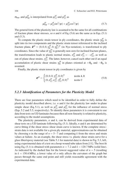
F<strong>in</strong>ally, the plastic stra<strong>in</strong> tensor <strong>in</strong> ply coord<strong>in</strong>ates is given by<br />
εεε pl =<br />
�<br />
(0,0,0,γ pl<br />
12 ,0,0)T mode A,B<br />
(0,ε pl<br />
22<br />
,ε pl<br />
33 ,γpl<br />
12 ,0,0)T mode C<br />
5.2.3 Identification of Parameters <strong>for</strong> the Plasticity Model<br />
(5.8)<br />
There are four parameters which need to be identified <strong>in</strong> order to fully def<strong>in</strong>e the<br />
plasticity model described above, i.e. n and k <strong>for</strong> the plasticity law under <strong>in</strong>-plane<br />
simple shear (Eq. 5.1), as well as µ pl<br />
12 and µpl<br />
23 <strong>for</strong> the <strong>in</strong>fluence of normal stress<br />
(Eqs. 5.2 and 5.5, respectively). To identify these parameters it is convenient to use<br />
data from tests on UD lam<strong>in</strong>ates because then all non-l<strong>in</strong>earity is related to plasticity,<br />
accord<strong>in</strong>g to the model assumptions.<br />
The plasticity parameters, n and k, can be derived from experimental data of<br />
shear tests on a UD lam<strong>in</strong>ate follow<strong>in</strong>g Eq. (5.1). Ideally, n and k are determ<strong>in</strong>ed by<br />
curve fitt<strong>in</strong>g if the shear stress–shear stra<strong>in</strong> curve is known. If the complete stress–<br />
stra<strong>in</strong> data is not available <strong>for</strong> a given ply material, approximations can be obta<strong>in</strong>ed<br />
by choos<strong>in</strong>g n <strong>in</strong> the range of n = 5−7 and comput<strong>in</strong>g k from the stress and stra<strong>in</strong><br />
values at failure. As an example, the shear stress vs. plastic shear stra<strong>in</strong> curve <strong>for</strong> a<br />
glass fiber/epoxy material (see Table 5.1 <strong>for</strong> material data) is shown <strong>in</strong> Fig. 5.3, left,<br />
us<strong>in</strong>g experimental data of a test on a hoop wound tube taken from [11]. The best fit<br />
us<strong>in</strong>g Eq. (5.1) is obta<strong>in</strong>ed with parameters n = 7.2andk = 120.7 MPa (solid l<strong>in</strong>e).<br />
As <strong>in</strong>dicated by the dashed l<strong>in</strong>e <strong>for</strong> the lowest suggested value of n = 5 (result<strong>in</strong>g<br />
<strong>in</strong> k = 150.6 MPa), a lower value of n only affects the curvature of the graph but<br />
passes through the same end po<strong>in</strong>t and still yields reasonable agreement with the<br />
experimental data.


