


Create successful ePaper yourself
Turn your PDF publications into a flip-book with our unique Google optimized e-Paper software.
Rev 2.02<br />
E4B01<br />
Frequency stability is a characteristic of a good harmonic frequency marker.<br />
E4B02<br />
Time base accuracy has the most affect on the accuracy of a frequency counter.<br />
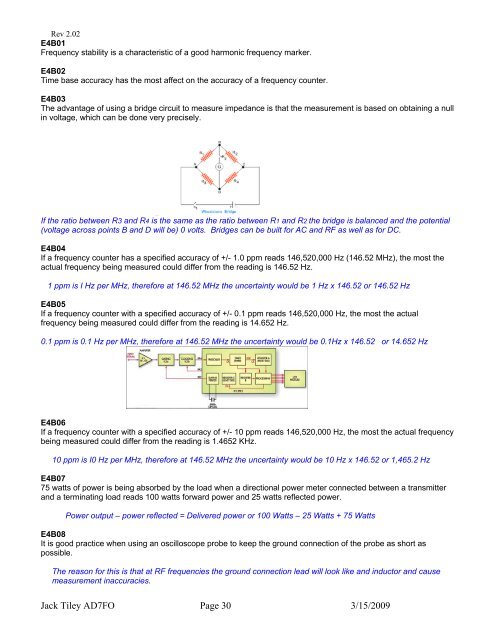
E4B03<br />
The advantage of using a bridge circuit to measure impedance is that the measurement is based on obtaining a null<br />
in voltage, which can be done very precisely.<br />
If the ratio between R3 and R4 is the same as the ratio between R1 and R2 the bridge is balanced and the potential<br />
(voltage across points B and D will be) 0 volts. Bridges can be built for AC and RF as well as for DC.<br />
E4B04<br />
If a frequency counter has a specified accuracy of +/- 1.0 ppm reads 146,520,000 Hz (146.52 MHz), the most the<br />
actual frequency being measured could differ from the reading is 146.52 Hz.<br />
1 ppm is I Hz per MHz, therefore at 146.52 MHz the uncertainty would be 1 Hz x 146.52 or 146.52 Hz<br />
E4B05<br />
If a frequency counter with a specified accuracy of +/- 0.1 ppm reads 146,520,000 Hz, the most the actual<br />
frequency being measured could differ from the reading is 14.652 Hz.<br />
0.1 ppm is 0.1 Hz per MHz, therefore at 146.52 MHz the uncertainty would be 0.1Hz x 146.52 or 14.652 Hz<br />
E4B06<br />
If a frequency counter with a specified accuracy of +/- 10 ppm reads 146,520,000 Hz, the most the actual frequency<br />
being measured could differ from the reading is 1.4652 KHz.<br />
10 ppm is I0 Hz per MHz, therefore at 146.52 MHz the uncertainty would be 10 Hz x 146.52 or 1,465.2 Hz<br />
E4B07<br />
75 watts of power is being absorbed by the load when a directional power meter connected between a transmitter<br />
and a terminating load reads 100 watts forward power and 25 watts reflected power.<br />
Power output – power reflected = Delivered power or 100 Watts – 25 Watts + 75 Watts<br />
E4B08<br />
It is good practice when using an oscilloscope probe to keep the ground connection of the probe as short as<br />
possible.<br />
The reason for this is that at RF frequencies the ground connection lead will look like and inductor and cause<br />
measurement inaccuracies.<br />
Jack Tiley <strong>AD7FO</strong> Page 30 3/15/2009