


Create successful ePaper yourself
Turn your PDF publications into a flip-book with our unique Google optimized e-Paper software.
Rev 2.02<br />
E9C03<br />
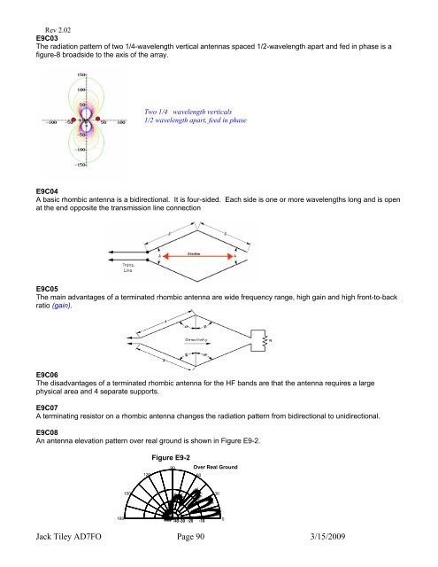
The radiation pattern of two 1/4-wavelength vertical antennas spaced 1/2-wavelength apart and fed in phase is a<br />
figure-8 broadside to the axis of the array.<br />
E9C04<br />
A basic rhombic antenna is a bidirectional. It is four-sided. Each side is one or more wavelengths long and is open<br />
at the end opposite the transmission line connection<br />
E9C05<br />
The main advantages of a terminated rhombic antenna are wide frequency range, high gain and high front-to-back<br />
ratio (gain).<br />
E9C06<br />
The disadvantages of a terminated rhombic antenna for the HF bands are that the antenna requires a large<br />
physical area and 4 separate supports.<br />
E9C07<br />
A terminating resistor on a rhombic antenna changes the radiation pattern from bidirectional to unidirectional.<br />
E9C08<br />
An antenna elevation pattern over real ground is shown in Figure E9-2.<br />
180<br />
150<br />
Two 1/4 wavelength verticals<br />
1/2 wavelength apart, feed in phase<br />
120<br />
Figure E9-2<br />
90<br />
Over Real Ground<br />
Jack Tiley <strong>AD7FO</strong> Page 90 3/15/2009<br />
60<br />
-40 -30 -20 -10<br />
30<br />
0