


You also want an ePaper? Increase the reach of your titles
YUMPU automatically turns print PDFs into web optimized ePapers that Google loves.
Rev 2.02<br />
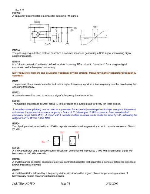
E7E13<br />
A frequency discriminator is a circuit for detecting FM signals<br />
E7E14<br />
The phasing or quadrature method describes a common means of generating a SSB signal when using digital<br />
signal processing.<br />
E7E15<br />
In a “direct conversion” software defined receiver incoming RF is mixed to “baseband” for analog-to-digital<br />
conversion and subsequent processing.<br />
E7F Frequency markers and counters: frequency divider circuits; frequency marker generators; frequency<br />
counters<br />
E7F01<br />
The purpose of a prescaler circuit is to divide a higher frequency signal so a low-frequency counter can display the<br />
operating frequency.<br />
E7F02<br />
A prescaler would be used to reduce a signal’s frequency by a factor of ten.<br />
E7F03<br />
The function of a decade counter digital IC is to produce one output pulse for every ten input pulses.<br />
A decade counter (divider) can be used as a prescaler for a counter (assuming it works high enough in frequency)<br />
to increase the counters frequency range by a factor of 10 (allowing a 10 MHz counter to have an extended<br />
frequency range to100 MHz). A circuit with 2 decade dividers in series would divide the input by 100, extending the<br />
range of our 10 MHz to 1,000 MHz<br />
E7F04<br />
Two flip-flops must be added to a 100-kHz crystal-controlled marker generator so as to provide markers at 50 and<br />
25 kHz.<br />
E7F05<br />
A 1 MHz oscillator and a decade counter circuit can be combined to produce a 100 kHz fundamental signal with<br />
harmonics at 100 kHz intervals.<br />
E7F06<br />
A crystal marker generator consists of a crystal-controlled oscillator that generates a series of reference signals at<br />
known frequency intervals<br />
E7F07<br />
A crystal oscillator followed by a frequency divider circuit would be a good choice for generating a series of<br />
harmonically related receiver calibration signals.<br />
Jack Tiley <strong>AD7FO</strong> Page 74 3/15/2009