


You also want an ePaper? Increase the reach of your titles
YUMPU automatically turns print PDFs into web optimized ePapers that Google loves.
Rev 2.02<br />
E9F11<br />
A 1/8-wavelength transmission line presents a capacitive reactance to a generator when the line is open at the far<br />
end.<br />
E9F12<br />
A 1/4-wavelength transmission line presents a very low impedance to a generator when the line is open at the far<br />
end.<br />
E9F13<br />
A 1/4-wavelength transmission line presents a very high impedance to a generator when the line is shorted at the<br />
far end.<br />
E9F14<br />
A 1/2-wavelength transmission line presents a very low impedance to a generator when the line is shorted at the far<br />
end.<br />
E9F15<br />
A 1/2-wavelength transmission line presents very high impedance to a generator when the line is open at the far<br />
end.<br />
E9F16<br />
The primary differences between foam-dielectric coaxial cable as opposed to solid-dielectric cable, assuming all<br />
other parameters are the same are reduced safe operating voltage limits, reduced losses per unit of length and<br />
higher velocity factor.<br />
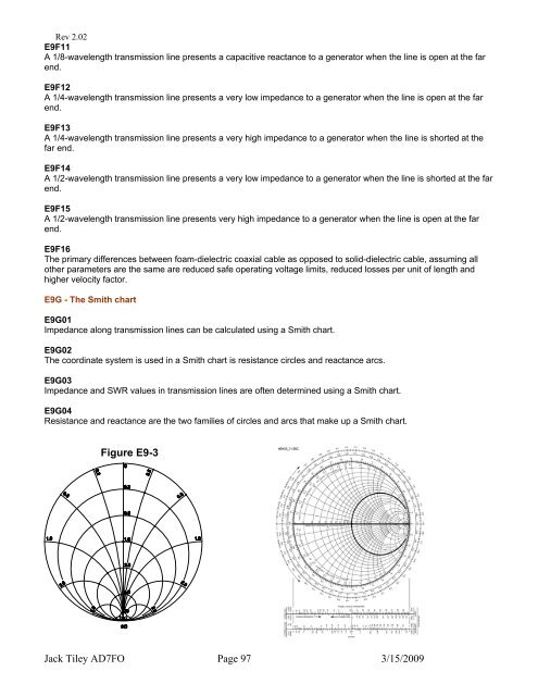
E9G - The Smith chart<br />
E9G01<br />
Impedance along transmission lines can be calculated using a Smith chart.<br />
E9G02<br />
The coordinate system is used in a Smith chart is resistance circles and reactance arcs.<br />
E9G03<br />
Impedance and SWR values in transmission lines are often determined using a Smith chart.<br />
E9G04<br />
Resistance and reactance are the two families of circles and arcs that make up a Smith chart.<br />
Figure E9-3<br />
Jack Tiley <strong>AD7FO</strong> Page 97 3/15/2009