


You also want an ePaper? Increase the reach of your titles
YUMPU automatically turns print PDFs into web optimized ePapers that Google loves.
Rev 2.02<br />
E7D02<br />
One characteristic of a switching electronic voltage regulator is the control device’s duty cycle is controlled to<br />
produce a constant average output voltage.<br />
E7D03<br />
A Zener diode is typically used as a stable reference voltage in a linear voltage regulator.<br />
E7D04<br />
A series regulator type of linear regulator makes the most efficient use of the primary power source.<br />
E7D05<br />
A shunt regulator type of linear voltage regulator places a constant load on the unregulated voltage source.<br />
C1<br />
4000<br />
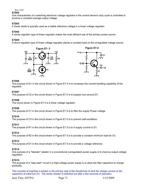
Figure E7- 3<br />
+25 Q1<br />
+12<br />
R1<br />
C2 D1<br />
4000<br />
C3<br />
0.01<br />
R2<br />
Figure E7-2<br />
E7D06<br />
The purpose of Q1 in the circuit shown in Figure E7-3 is to increases the current-handling capability of the<br />
regulator.<br />
E7D07<br />
The purpose of C2 in the circuit shown in Figure E7-3 is to bypass hum around D1.<br />
E7D08<br />
The circuit shown in Figure E7-3 is a linear voltage regulator.<br />
E7D09<br />
The purpose of C1 in the circuit shown in Figure E7-3 is to filter the supply Power voltage.<br />
E7D10<br />
The purpose of C3 in the circuit shown in Figure E7-3 is to prevent self-oscillation.<br />
E7D11<br />
The purpose of R1 in the circuit shown in Figure E7-3 is to It supply current to D1.<br />
E7D12<br />
The purpose of R2 in the circuit shown in Figure E7-3 is to provide a constant minimum load for Q1.<br />
E7D13<br />
The purpose of D1 in the circuit shown in Figure E7-3 is to provide a voltage reference.<br />
E7D14<br />
One purpose of a "bleeder" resistor in a conventional (unregulated) power supply is to improve output voltage<br />
regulation.<br />
E7D15<br />
The purpose of a "step-start" circuit in a high-voltage power supply is to allow the filter capacitors to charge<br />
gradually.<br />
This consists of inserting a resistor in the primary side of the transformer to limit the charge current on the<br />
capacitors at initial turn on. The series resistor is switched out after a few seconds of operation.<br />
Jack Tiley <strong>AD7FO</strong> Page 71 3/15/2009<br />
R<br />
C2<br />
C1