V - Faggiolati Pumps
V - Faggiolati Pumps
V - Faggiolati Pumps

You also want an ePaper? Increase the reach of your titles
YUMPU automatically turns print PDFs into web optimized ePapers that Google loves.
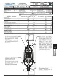
Sistema di raffreddamento<br />
Cooling system<br />
Système de refroidissement<br />
Kühlungssystem<br />
Sistema de enfriamiento<br />
Sistema de arrefecimento<br />
Innovativo sistema di raffreddamento tramite la circolazione<br />
forzata a circuito chiuso di liquido refrigerante tra la carcassa<br />
della pompa e la camicia di raffreddamento esterna, grazie ad una<br />
girante centrifuga ausiliaria calettata direttamente sull’albero.<br />
Lo schema di intercambiabilità proposto prevede la possibilità di<br />
realizzare motori con raffreddamento forzato tramite una girante<br />
ausiliaria (1).<br />
La circolazione del liquido di raffreddamento è realizzata attraverso un<br />
particolare disco di separazione (2) che viene montato nella camera olio<br />
e che la divide in due zone una di aspirazione (3) ed una di mandata (4).<br />
Il liquido refrigerante raffreddato dal contatto con il disco porta-tenuta (5),<br />
viene aspirato dalla girante di circolazione a ridosso della tenuta<br />
meccanica lato acqua ed inviato attraverso quattro fori (6) alla parte<br />
inferiore della carcassa statorica, da cui percorrendo lo spazio anulare<br />
tra carcassa e camicia risale verso la testata.<br />
Il percorso di ritorno del fluido caldo è effettuato tramite quattro tubi di<br />
acciaio inossidabile (7) che lo riportano nella zona inferiore della camera<br />
olio.<br />
La camera olio e la carcassa statorica sono realizzate in modo tale da<br />
poter utilizzare lo stesso grezzo di fusione sia per la realizzazione del<br />
motore con raffreddamento a convezione forzata, sia per la realizzazione<br />
del motore con raffreddamento a convezione naturale.<br />
Refrigerant forced in close circuit between the motor casing<br />
and the external cooling jacket secured by a centrifugal<br />
impeller direct connected on the shaft.<br />
The refrigerant fluid is forced between the external pump body and the<br />
cooling jacket by one auxiliary impeller directly coupled on the main<br />
pump shaft (1).<br />
The working principle do permit to cool the motor by a forced feed<br />
lubrication system.<br />
A specific intermediate disk is mounted in the oil chamber (2).<br />
By this mean we have in the lower part a suction side (3) and in the upper<br />
part of the disk the discharge side (4).<br />
The fluid is cooled by the transfer of heat to the seal-housing (5).<br />
The refrigerant fluid is than pumped through four channels in the<br />
intermediate cooling chamber (6) existing between the external pump<br />
body and the motor toward the upper part of the pump.<br />
The return circuit of the fluid towards the down-part of the disk in the oil<br />
chamber is done by four stainless steel tubing (7) located inside to the<br />
interference space enclosed between the external pump body and the<br />
outside stainless steel jacket of the pump.<br />
Innovateur système de refroidissement par circulation<br />
forcée en circuit fermé de liquide réfrigérant entre la<br />
carcasse de la pompe et la chemise de refroidissement externe, grâce à<br />
un rotor centrifuge auxiliaire à prise directe sur l'arbre.<br />
Le schéma d'interchangeabilité proposé prévoit la possibilité de réaliser<br />
des moteurs avec refroidissement forcé par rotor auxiliaire (1).<br />
La circulation du liquide de refroidissement est réalisée à travers un<br />
disque spécial de séparation (2) qui est monté sur la chambre à huile et<br />
qui la divise en deux zones, une d'aspiration (3) et une de refoulement<br />
(4). Le liquide réfrigérant refroidi par le contact avec le disque porte-joint<br />
(5) est aspiré par le rotor de circulation situé tout près du joint d'étanchéité<br />
mécanique côté eau et envoyé à travers les quatre orifices (6) à la partie<br />
inférieure de la carcasse stator, d'où il ressort, en parcourant l'espace<br />
annulaire entre la carcasse et la chemise, vers l'extrémité.<br />
Le parcours de retour du fluide chaud s'effectue à travers quatre tuyaux<br />
d'acier inoxydable (7) qui le reportent dans la zone inférieure de la<br />
chambre à huile.<br />
La chambre à huile et la carcasse stator sont fabriquées de façon à<br />
pouvoir utiliser le même brut de fusion tant pour la fabrication du moteur à<br />
refroidissement par convection forcée que pour la fabrication du moteur à<br />
refroidissement par convection naturelle.<br />
329