pg _ pga series - Stoewer-Getriebe.de
pg _ pga series - Stoewer-Getriebe.de
pg _ pga series - Stoewer-Getriebe.de

Create successful ePaper yourself
Turn your PDF publications into a flip-book with our unique Google optimized e-Paper software.
Queste informazioni permettono<br />
una prima scelta <strong>de</strong>i riduttori<br />
dopo aver <strong>de</strong>terminato:<br />
• rapporto di trasmissione i<br />
• coppia di lavoro M [kNm]<br />
• carichi sull’albero in uscita e<br />
in entrata al riduttore Fr; Fa<br />
[N]<br />
Successivamente si dovrà proce<strong>de</strong>re<br />
alle verifiche <strong>de</strong>i parametri<br />
caratteristici <strong>de</strong>i riduttori<br />
come segue:<br />
I) velocità in ingresso al<br />
riduttore ≤ n1 max<br />
II) coppia di lavoro ≤ Mc<br />
III) carichi applicati all’albero in<br />
uscita e in entrata ≤ Fr;Fa<br />
IV) potenza da trasmettere ≤ Pt<br />
(se in servizio continuo)<br />
V) temperatura ambiente<br />
Le relazioniIeVsono di<br />
immediata verifica mentre per la<br />
II, la III e la IV si proce<strong>de</strong> come<br />
segue:<br />
VERIFICA DEL RIDUTTORE<br />
IN FUNZIONE DELLA COPPIA<br />
Calcolo <strong>de</strong>lla coppia equivalente<br />
Me [kNm]<br />
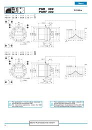
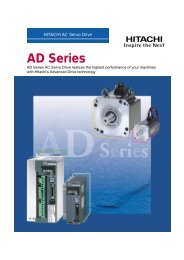
Quando il carico è variabile nel<br />
tempo (Istogramma 1), si <strong>de</strong>ve<br />
<strong>de</strong>terminare il valore <strong>de</strong>lla coppia<br />
equivalente.<br />
Con il criterio <strong>de</strong>l cumulativo di<br />
carico si calcola, con la formula<br />
sotto indicata, la coppia in grado<br />
di provocare lo stesso livello<br />
di usura dopo il numero di cicli<br />
(nxh) richiesto dal progetto.<br />
10<br />
Istogramma 1<br />
Histogram 1<br />
Histogramme 1<br />
Histogramm 1<br />
M<br />
M1<br />
Me<br />
M2<br />
M3<br />
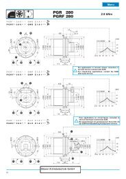
CARATTERISTICHE TECNICHE<br />
TECHNICAL INFORMATION<br />
CARACTERISTIQUES TECHNIQUES<br />
TECHNISCHE EIGENSCHAFTEN<br />
By means of this information it<br />
becomes possible to proceed to<br />
an initial planetary unit selection<br />
after <strong>de</strong>termining:<br />
• reduction ratio i<br />
• working torque M [kNm]<br />
• loads on planetary unit<br />
output and input shaft Fr; Fa<br />
[N]<br />
Subsequently, we are to verify<br />
some distinctive parameters of<br />
the planetary unit as follows:<br />
I) input rotation peed ≤n1 max<br />
II) working torque ≤ Mc<br />
III) loads on output and input<br />
shafts ≤ Fr;Fa<br />
IV) horsepower to be transmitted<br />
≤ Pt (if un<strong>de</strong>r continuous<br />
duty)<br />
V) room temperature<br />
Relations I and V can be readily<br />
verified; as for relations II, III<br />
and IV we must proceed as<br />
follows:<br />
VERIFICATION OF THE PLAN-<br />
ETARY UNIT ACCORDING TO<br />
THE TORQUE<br />
Calculation of the equivalent<br />
working torque Me [kNm]<br />
When loads are intermittent<br />
(see Histogram 1), it is necessary<br />
to <strong>de</strong>termine the value of<br />
the equivalent working torque.<br />
We adopt the principle of cumulative<br />
load and <strong>de</strong>termine the<br />
torque value which produces<br />
the same fatigue after the number<br />
of cycles (nxh) required by<br />
the project, by means of the following<br />
formula:<br />
6<br />
Ces informations nous permettent<br />
une première selection du<br />
réducteur après avoir déterminé:<br />
• le rapport <strong>de</strong> transmission i<br />
• le couple <strong>de</strong> travail M [kNm]<br />
• les charges sur l’arbre <strong>de</strong><br />
sortie et d'entrée du réducteur<br />
Fr; Fa [N]<br />
Par la suite il faudra vérifier certains<br />
paramètres distinctifs <strong>de</strong>s<br />
réducteurs, notamment:<br />
I) Vitesse d’entrée ≤ n1 max<br />
II) Couple <strong>de</strong> travail ≤ Mc<br />
III) Charges sur l’arbre <strong>de</strong> sortie<br />
et d'entrée ≤ Fr;Fa<br />
IV) Puissance à transmettre<br />
≤ Pt (si le service est<br />
continu)<br />
V) température ambiante<br />
Les relations I et V peuvent être<br />
immédiatement vérifiées, alors<br />
que pour les relations II, III et IV<br />
on doit procé<strong>de</strong>r comme suit:<br />
VERIFICATION DU REDUC-<br />
TEUR PAR RAPPORT AU<br />
COUPLE<br />
Calcul du couple equivalent<br />
Me [kNm]<br />
Lorsque les charges sont intermittentes<br />
(voir Histogramme 1),<br />
il faut déterminer la valeur du<br />
couple équivalent.<br />
On adopte le principe du cumul<br />
<strong>de</strong>s charges et, au moyen <strong>de</strong> la<br />
formule ci-<strong>de</strong>ssous, on trouve<br />
la valeur du couple qui détermine<br />
le même niveau d’usure<br />
pour le nombre <strong>de</strong> cycles (nxh)<br />
requis par le projet.<br />
( n x h ) ( n x h ) ( n x h )<br />
( n x h) ( n x h) ( n x h)<br />
1 1<br />
2 2 3 3<br />
6 6 6<br />
3<br />
Me = M1 + M2 + M<br />
nxh 1 1 nxh 2 2 nxh 3 3<br />
0.1 0.2 0.3 0.4 0.5 0.6 0.7 0.8 0.9 1<br />
nxh<br />
STÖWER ANTRIEBSTECHNIK GMBH<br />
Menu<br />
Diese Daten ermöglichen eine<br />
erste Auswahl <strong>de</strong>s <strong>Getriebe</strong>s<br />
und zwar nach <strong>de</strong>r Festlegung<br />
von:<br />
• Übersetzung i<br />
• Arbeitsdrehmoment M [kNm]<br />
• Belastung an <strong>de</strong>r Abtriebs- und<br />
Antriebswelle Fr, Fa [N]<br />
Danach sind folgen<strong>de</strong> Parameter<br />
zu überprüfen:<br />
I) <strong>Getriebe</strong>drehzahl ≤ n1 max<br />
II) Betriebsdrehmoment ≤ Mc<br />
III) Belastungen auf <strong>de</strong>r<br />
Abtriebswelle und<br />
Antriebswelle ≤ Fr;Fa<br />
IV) Wärmeleistung ≤ Pt<br />
(Dauerbetrieb)<br />
V) Umgebungstemperatur<br />
Die Parameter I und V kann<br />
man ohne weiteres prüfen. Was<br />
II, III und IV betrifft, ist wie folgt<br />
vorzugehen:<br />
ÜBERPRÜFUNG DES GE-<br />
TRIEBES AUFGRUND DES<br />
DREHMOMENTS<br />
Berechnung <strong>de</strong>s equivalenten<br />
Drehmoments Me [kNm]<br />
Wenn die Belastung während<br />
<strong>de</strong>r Einsatzdauer variiert (siehe<br />
z.B. Diagramm 1), soll man einen<br />
Durchschnittswert ermitteln.<br />
Nach <strong>de</strong>m Lastkollektiv wird<br />
das Drehmoment mit <strong>de</strong>r unten<br />
angegebenen Formel berechnet.