Méthode XFEM pour la Modélisation de grandes ... - Cast3M - CEA
Méthode XFEM pour la Modélisation de grandes ... - Cast3M - CEA
Méthode XFEM pour la Modélisation de grandes ... - Cast3M - CEA
You also want an ePaper? Increase the reach of your titles
YUMPU automatically turns print PDFs into web optimized ePapers that Google loves.
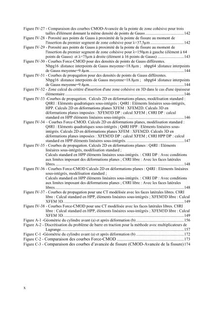
Figure IV-27 - Comparaison <strong>de</strong>s courbes CMOD-Avancée <strong>de</strong> <strong>la</strong> pointe <strong>de</strong> zone cohésive <strong>pour</strong> trois<br />
tailles d'élément donnant <strong>la</strong> même <strong>de</strong>nsité <strong>de</strong> points <strong>de</strong> Gauss ......................................142<br />
Figure IV-28 - Porosité aux points <strong>de</strong> Gauss à proximité <strong>de</strong> <strong>la</strong> pointe <strong>de</strong> fissure au moment <strong>de</strong><br />
l'insertion du premier segment <strong>de</strong> zone cohésive <strong>pour</strong> λ=37,5µm .................................142<br />
Figure IV-29 - Porosité aux points <strong>de</strong> Gauss à proximité <strong>de</strong> <strong>la</strong> pointe <strong>de</strong> fissure au moment <strong>de</strong><br />
l'insertion du premier segment <strong>de</strong> zone cohésive <strong>pour</strong> λ=150µm à gauche (élément à 64<br />
points <strong>de</strong> Gauss) et λ=75µm à droite (élément à 16 points <strong>de</strong> Gauss) ..........................143<br />
Figure IV-30 - Courbes Force-CMOD <strong>pour</strong> <strong>de</strong>s <strong>de</strong>nsités <strong>de</strong> points <strong>de</strong> Gauss différentes.<br />
Nbpg16 :distance interpoints <strong>de</strong> Gauss moyenne=18.8µm ; nbpg64 :distance interpoints<br />
<strong>de</strong> Gauss moyenne=9.4µm.............................................................................................144<br />
Figure IV-31 - Courbes <strong>de</strong> propagation <strong>pour</strong> <strong>de</strong>s <strong>de</strong>nsités <strong>de</strong> points <strong>de</strong> Gauss différentes.<br />
Nbpg16 :distance interpoints <strong>de</strong> Gauss moyenne=18.8µm ; nbpg64 :distance interpoints<br />
<strong>de</strong> Gauss moyenne=9.4µm.............................................................................................144<br />
Figure IV-32 - Zone calcul du critère d'insertion d'une zone cohésive en 3D dans le cas d'une épaisseur<br />
élémentaire.....................................................................................................................146<br />
Figure IV-33 -Courbes <strong>de</strong> propagation. Calculs 2D en déformations p<strong>la</strong>nes, modélisation standard :<br />
Q8RI : Eléments quadratiques sous-intégrés ; Q4RI : Eléments linéaires sous-intégrés,<br />
HPP. Calculs 2D en déformations p<strong>la</strong>nes <strong>XFEM</strong> : <strong>XFEM</strong>2D. Calculs 3D en<br />
déformations p<strong>la</strong>nes imposées : <strong>XFEM</strong>3D DP : calcul <strong>XFEM</strong> ; C8RI DP : calcul<br />
standard en HPP éléments linéaires sous-intégrés. ........................................................146<br />
Figure IV-34 – Courbes Force-CMOD. Calculs 2D en déformations p<strong>la</strong>nes, modélisation standard :<br />
Q8RI : Eléments quadratiques sous-intégrés ; Q4RI HPP : Eléments linéaires sousintégrés.<br />
Calculs 2D en déformations p<strong>la</strong>nes <strong>XFEM</strong> : <strong>XFEM</strong>2D. Calculs 3D en<br />
déformations p<strong>la</strong>nes imposées : <strong>XFEM</strong>3D DP : calcul <strong>XFEM</strong> ; C8RI HPP DP : calcul<br />
standard en HPP éléments linéaires sous-intégrés. ........................................................147<br />
Figure IV-35 - Courbes <strong>de</strong> propagation. Calculs 2D en déformations p<strong>la</strong>nes : Q4RI : Eléments<br />
linéaires sous-intégrés, modélisation standard ;<br />
Calculs standard en HPP éléments linéaires sous-intégrés. : C8RI DP : Avec conditions<br />
aux limites imposant <strong>de</strong>s déformations p<strong>la</strong>nes ; C8RI libre : Avec les faces <strong>la</strong>térales<br />
libres...............................................................................................................................148<br />
Figure IV-36 - Courbes Force-CMOD Calculs 2D en déformations p<strong>la</strong>nes : Q4RI : Eléments linéaires<br />
sous-intégrés, modélisation standard ;<br />
Calculs standard en HPP éléments linéaires sous-intégrés. : C8RI DP : Avec conditions<br />
aux limites imposant <strong>de</strong>s déformations p<strong>la</strong>nes ; C8RI libre : Avec les faces <strong>la</strong>térales<br />
libres...............................................................................................................................148<br />
Figure IV-37 - Courbes <strong>de</strong> propagation <strong>pour</strong> une CT modélisée avec les faces <strong>la</strong>térales libres. C8RI<br />
libre : Calcul standard en HPP, éléments linéaires sous-intégrés ; <strong>XFEM</strong>3D libre : Calcul<br />
<strong>XFEM</strong> 3D.......................................................................................................................149<br />
Figure IV-38 - Courbes Force-CMOD <strong>pour</strong> une CT modélisée avec les faces <strong>la</strong>térales libres. C8RI<br />
libre : Calcul standard en HPP, éléments linéaires sous-intégrés ; <strong>XFEM</strong>3D libre : Calcul<br />
<strong>XFEM</strong> 3D.......................................................................................................................149<br />
Figure A-1 -Géométrie du cylindre avant (a) et après déformation (b) ...............................................156<br />
Figure A-2 - Discrétisation du problème <strong>de</strong> barre en traction <strong>pour</strong> <strong>la</strong> métho<strong>de</strong> avec multiplicateurs <strong>de</strong><br />
Lagrange.........................................................................................................................157<br />
Figure C-1 -Géométrie du cylindre avant (a) et après déformation (b) ...............................................172<br />
Figure C-2 - Comparaison <strong>de</strong>s courbes Force-CMOD ..................................................................173<br />
Figure C-3 - Comparaison <strong>de</strong>s courbes d’avancée <strong>de</strong> fissure (CMOD-Avancée <strong>de</strong> <strong>la</strong> fissure)174<br />
x


