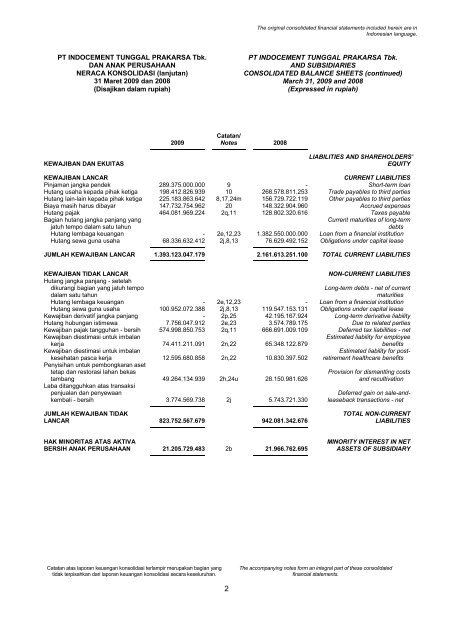
March 2009 - Indocement Tunggal Prakarsa, PT.
March 2009 - Indocement Tunggal Prakarsa, PT.
March 2009 - Indocement Tunggal Prakarsa, PT.
- No tags were found...

You also want an ePaper? Increase the reach of your titles
YUMPU automatically turns print PDFs into web optimized ePapers that Google loves.
SPECIFICATIONS ELECTRIC CONVECTION OVENSSPECIFICATIONSSPECIFICATIONSNOTICEThe appliance, when installed, must be electrically grounded and comply with local codes, or in theabsence of local codes, with the National Electrical Code, ANSI/NFPA 70, or the Canadian ElectricalCode, CSA C22.2, as applicable.Southbend reserves the right to change specifications and product design without notice. Suchrevisions do not entitle the buyer to corresponding changes, additions, or replacements for previouslypurchased equipment.This product is intended for commercial use only, not for household use.ELECTRICITY SUPPLYThe following table lists the electricity supply requirements PER OVEN (double for dual-oven models).Nominal Amperes per Line-WireSupplyTotal 3-Phase Loading (kW/phase)Oven Component3-Phase1-PhaseVoltagekWL1-L2 L2-L3 L1-L3 L1 L2 L3 Total480Heating Elements 11.00 3.67 3.67 3.67 13.2 13.2 13.2 22.9Motor & Controls 0.90 0.00 0.00 0.00 2.2 0.0 2.2 2.2415Heating Elements 11.00 3.67 3.67 3.67 15.3 15.3 15.3 45.9Motor & Controls 0.90 0.00 L3-N 0.90 0.0 0.0 3.8 3.8380Heating Elements 11.00 3.67 3.67 3.67 16.7 16.7 16.7 28.9Motor & Controls 0.90 0.00 L3-N 0.90 0.0 0.0 4.1 4.1240Heating Elements 11.00 3.67 3.67 3.67 26.4 26.4 26.4 45.8Motor & Controls 0.90 0.00 0.00 0.90 3.8 0.0 3.8 3.8220 Heating Elements 9.25 3.10 3.10 3.10 24.2 24.2 24.2 42.0(50Hz) Motor & Controls 0.90 0.00 0.00 0.90 4.1 0.0 4.1 4.1208Heating Elements 11.00 3.67 3.67 3.67 30.5 30.5 30.5 52.9Motor & Controls 0.90 0.00 0.00 0.90 4.3 0.0 4.3 4.3Minimum SupplyWire (AWG) Size3-Phase 1-Phase12 1012 612 88 68 68 4An electrical diagram is located on the side of the control panel assembly (see drawing on page 42).Electrical diagrams can also be found in this manual beginning on page 43.The electrical connections are made directly to the terminals of the heating-element contactor, which islocated inside the control-panel compartment on the right side of the oven. A circular opening sized for astrain-relief fitting is located on the back of the oven near the right side (right as seen from the front of theoven, see illustration on page 19). Models with two stacked ovens have a separate electrical connection foreach oven.Use 167°F (75°C) wire for all supply lines.Ovens are shipped wired for either single-phase or three-phase operation, depending on which wasspecified on the factory order. If necessary, an oven can be field-converted to use either single-phase orthree-phase power (see page 39).PAGE 4 OPERATOR’S MANUAL 1181958 REV 2