english
english
english

Create successful ePaper yourself
Turn your PDF publications into a flip-book with our unique Google optimized e-Paper software.
ENGLISH<br />
42<br />
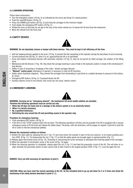
4.3 LOWERING OPERATIONS<br />
Follow these instructions:<br />
• Turn the emergency button (18 Fig. 2) as indicated by the arrow and bring it in raised position.<br />
• Push the reset/ON button (19 Fig. 2).<br />
• Press the DOWN push-button (22 Fig. 2) and bring the carriages to the minimum height.<br />
• Push deeply the emergency/OFF button (18 Fig. 2).<br />
• Rotate the arms so that they do not get in the way of the motor-vehicle as it is leaves the lift and close the extensions.<br />
• Move the vehicle from the hoist area.<br />
4.4 SAFETY DEVICES<br />
WARNING: Do not absolutely remove or tamper with these devices. They must be kept in full efficiency all the time:<br />
• Anti-toe trapping devices applied to the arms (13 Fig. 2) prevent the feet squashing of the operator during the last phase of arms lowering.<br />
• Current presence led (20 Fig. 2): when it is on, approaching the lift is no permitted.<br />
• Arms anti-rotation mechanical devices with automatic insertion (14 Fig. 2): they do not permit by lifted carriage, the rotation of the lifting<br />
arms.<br />
• Mechanical anti-fall devices (1 Fig. 18): they block the carriage lowering in case of leak in the hydraulic system or break of the mechanical lifting<br />
devices.<br />
• Safety in case of loosening or breakage of the chain: blocks carriages descent.<br />
• “Manned” control panel: attendance of operator is necessary to start all lift functions.<br />
• Safety valves (hydraulic diagram): They prevent the carriages from descending in case there is a sudden decrease in pressure in the hydraulic<br />
circuit.<br />
• Emergency/OFF button (18 Fig. 2): if pressed blocks the lift.<br />
• Auxiliary electric circuit in low tension: this circuit can not cause “electric shock".<br />
4.5 EMERGENCY LOWERING<br />
WARNING: Carrying out an “emergency descent”, the mechanical fall-proof saddle safeties are excluded.<br />
Therefore the following operations must be carried out only:<br />
• When the lift does not lower due to a damage in the electric system or to an electricity failure;<br />
• When it is strictly necessary;<br />
• By a qualified technician;<br />
• Delimiting the area around the lift and permitting access to the operator only.<br />
Procedure for emergency lowering:<br />
• Push emergency/OFF button (18 Fig. 2).<br />
• If the lift is in the “STOP" position these will not open. The following operations will then only be possible if the lift is equipped with a manual<br />
emergency pump to lift the hoist and release the safety stops. The pump, with use directions, will be supply on request. It permit to raise the<br />
lift in order to free the mechanical safeties.<br />
Release the mechanical safeties as follows:<br />
1) Stretch the steel cable by releasing the nut (1 Fig. 17) and move down the cylinder in each of the two columns to its lowest possible position<br />
(POS. B Fig. 17). Fix temporarely the nut (1 Fig. 17) so that the safety pawls are brought again in opened position (Fig. 17).<br />
2) Release again the knurled screw (6 Fig. 13). Screwing or unscrewing the screw increases or decreases the lowering speed of the carriages.<br />
3) When the operation is terminated, screw in the screw (6 Fig. 13) again.<br />
4) When the lowering operation is completed, release again the nut (1 Fig. 17) and feed the pneumatic circuit of the lift. This will allow to realign<br />
vertically the pneumatic piston of each column and to take it back to the original position (POS. A Fig. 17). Lock the again the nut.<br />
DANGER: Carry out with accurancy all operations of point 2.<br />
CAUTION: When you have reset the normal operating of the lift, let the unloaded hoist to go up and down for 2 or 3 times and check the<br />
functioning of the safety devices described in point 5.1.2.