shot peening residual stress - Metal Improvement Company
shot peening residual stress - Metal Improvement Company
shot peening residual stress - Metal Improvement Company

You also want an ePaper? Increase the reach of your titles
YUMPU automatically turns print PDFs into web optimized ePapers that Google loves.
T A B L E O F C O N T E N T S<br />
T A B L E O F C O N T E N T S<br />
Conversion Tables................................................................................. 2,3<br />
Introduction ............................................................................................. 5<br />
CHAPTER 1 :<br />
THEORY<br />
The Shot Peening Process........................................................................ 6<br />
Shot Peening Residual Stress .................................................................. 7<br />
Summation of Applied and Residual Stress ............................................. 8<br />
Application Case Study: NASA Langley Crack Growth Study .................... 8<br />
Depth of Residual Stress.......................................................................... 9<br />
Shot Peening Media ................................................................................. 9<br />
Effect of Shot Hardness............................................................................ 9<br />
CHAPTER 2 :<br />
RESPONSE OF METALS<br />
High Strength Steels .............................................................................. 10<br />
Carburized Steels.................................................................................... 11<br />
Application Case Study: High Performance Crankshafts ......................... 11<br />
Decarburization ...................................................................................... 11<br />
Application Case Study: Reduction of Retained Austenite...................... 12<br />
Austempered Ductile Iron....................................................................... 12<br />
Cast Iron................................................................................................. 12<br />
Aluminum Alloys..................................................................................... 13<br />
Application Case Study: High Strength Aluminum.................................. 13<br />
Titanium ................................................................................................. 14<br />
Magnesium............................................................................................. 14<br />
Powder <strong>Metal</strong>lurgy ................................................................................. 15<br />
Application Case Study: High Density Powder <strong>Metal</strong> Gears.................... 15<br />
CHAPTE R 3 :<br />
MANUFACTURING PROCESSES<br />
Effect on Fatigue Life .............................................................................. 16<br />
Welding .................................................................................................. 16<br />
Application Case Study: Fatigue of Offshore Steel Structures ................ 17<br />
Application Case Study: Turbine Engine HP Compressor Rotors ............ 17<br />
Grinding ................................................................................................. 18<br />
Plating .................................................................................................... 18<br />
Anodizing ............................................................................................... 19<br />
Application Case Study: Anodized Aluminum Rings............................... 19<br />
Plasma Spray.......................................................................................... 19<br />
Electro-Discharge Machining (EDM) ....................................................... 19<br />
Electro-Chemical Machining (ECM) ........................................................ 20<br />
Application Case Study: Diaphragm Couplings...................................... 20<br />
CHAPTER 4 :<br />
BENDING FAT IGUE<br />
Bending Fatigue ..................................................................................... 21<br />
Gears...................................................................................................... 21<br />
Connecting Rods.................................................................................... 22<br />
Crankshafts............................................................................................ 23<br />
Application Case Study: Diesel Engine Crankshafts............................... 23<br />
Application Case Study: Turbine Engine Disks....................................... 23<br />
CHAPTER 5 :<br />
TORSIONAL FATIGUE<br />
Torsional Fatigue.................................................................................... 24<br />
Compression Springs............................................................................. 24<br />
Drive Shafts ........................................................................................... 25<br />
Torsion Bars........................................................................................... 25<br />
Application Case Study: Automotive Torsion Bars ................................. 25<br />
CHAPTER 6 :<br />
AXIAL FATIGUE<br />
Axial Fatigue .......................................................................................... 26<br />
Application Case Study: Train Emergency Brake Pin.............................. 26<br />
Application Case Study: Auxiliary Power Unit (APU) Exhaust Ducts....... 26<br />
www.metalimprovement.com<br />
CHAPTER 7 :<br />
CONTACT FAILURE<br />
Fretting Failure....................................................................................... 27<br />
Application Case Study: Turbomachinery Blades and Buckets............... 27<br />
Pitting .....................................................................................................27<br />
Galling ................................................................................................... 28<br />
CHAPTER 8 :<br />
CORROSION FAILURE<br />
Corrosion Failure.................................................................................... 29<br />
Stress Corrosion Cracking...................................................................... 29<br />
Application Case Study: Fabrication of Chemical Handling Equipment .... 30<br />
Corrosion Fatigue................................................................................... 30<br />
Application Case Study: Sulfide Stress Cracking.................................... 30<br />
Application Case Study: Medical Implants ............................................. 31<br />
Intergranular Corrosion .......................................................................... 31<br />
CHAPTER 9 :<br />
THERMAL FATIGUE & HEAT EFFECTS<br />
Effects of Heat ....................................................................................... 32<br />
Thermal Fatigue ..................................................................................... 33<br />
Application Case Study: Feedwater Heaters........................................... 33<br />
CHAPTE R 10:<br />
OTHER APPLICATIONS<br />
Peen Forming ......................................................................................... 34<br />
Contour Correction................................................................................. 35<br />
Work Hardening ..................................................................................... 35<br />
Peentex sm ............................................................................................... 36<br />
Engineered Surfaces .............................................................................. 36<br />
Application Case Study: Pneumatic Conveyor Tubing............................ 37<br />
Application Case Study: Food Industry .................................................. 37<br />
Exfoliation Corrosion.............................................................................. 38<br />
Porosity Sealing..................................................................................... 38<br />
CHAPTER 11:<br />
ADDITIONAL C APABILITIES & SERVICES<br />
Internal Surfaces and Bores................................................................... 39<br />
Dual (Intensity) Peening ........................................................................ 39<br />
The C.A.S.E. sm Process ............................................................................ 40<br />
On-Site Shot Peening ............................................................................. 41<br />
Strain Peening ........................................................................................ 41<br />
Peen<strong>stress</strong> sm Residual Stress Modeling .................................................. 42<br />
Laser<strong>shot</strong> sm Peening ............................................................................... 43<br />
Valve Reeds – Manufacturing................................................................. 43<br />
Reprints/Technical Articles .................................................................... 44<br />
Heat Treating ......................................................................................... 44<br />
CHAPTER 12:<br />
CONTROLLING THE PROCESS<br />
Controlling the Process.......................................................................... 45<br />
Media Control ........................................................................................ 45<br />
Intensity Control .................................................................................... 46<br />
Coverage Control ................................................................................... 47<br />
Automated Shot Peening Equipment ..................................................... 48<br />
Application Case Study: CMSP Increases Turbine Engine Service Life ...... 49<br />
Specifying Shot Peening ........................................................................ 50<br />
MIC Technical Reprints ..................................................................... 51-55<br />
MIC Facility Listings ................................................................ Back Cover<br />
1
C O N V E R S I O N S<br />
2<br />
Approximate Conversion from Hardness to Tensile Strength of Steels<br />
Rockwell Brinell Vickers Tensile Tensile<br />
Hardness Hardness Hardness Strength Strength<br />
HRC BHN HV ksi MPa<br />
62 688 746 361 2489<br />
61 668 720 349 2406<br />
60 649 697 337 2324<br />
59 631 674 326 2248<br />
58 613 653 315 2172<br />
57 595 633 305 2103<br />
56 577 613 295 2034<br />
55 559 595 286 1972<br />
54 542 577 277 1910<br />
53 525 560 269 1855<br />
52 509 544 261 1800<br />
51 494 528 253 1744<br />
50 480 513 245 1689<br />
49 467 498 238 1641<br />
48 455 484 231 1593<br />
47 444 471 224 1544<br />
46 433 458 217 1496<br />
45 422 446 211 1455<br />
44 411 434 206 1420<br />
43 401 423 201 1386<br />
42 391 412 196 1351<br />
41 381 402 191 1317<br />
40 371 392 186 1282<br />
39 361 382 181 1248<br />
38 352 372 176 1214<br />
37 343 363 171 1179<br />
36 334 354 166 1145<br />
35 325 345 162 1117<br />
34 317 336 158 1089<br />
33 309 327 154 1062<br />
32 301 318 150 1034<br />
31 293 310 146 1007<br />
30 286 302 142 979<br />
29 279 294 138 952<br />
28 272 286 134 924<br />
27 265 279 130 896<br />
26 259 272 127 876<br />
25 253 266 124 855<br />
24 247 260 121 834<br />
23 241 254 118 814<br />
22 235 248 116 800<br />
21 229 243 113 779<br />
20 223 238 111 765<br />
www.metalimprovement.com
Common Conversions Associated with Shot Peening<br />
Metric (SI) to English (US Customary) English to Metric<br />
Length 1 mm = 0.0394 in 1 in = 25.4 mm<br />
1 m = 3.281 ft = 39.37 in 1 ft = 0.3048 m = 304.8 mm<br />
Area 1 mm 2 = 1.550 x 10 –3 in 2 1 in 2 = 645.2 mm 2<br />
1 m 2 = 10.76 ft 2 1 ft 2 = 92.90 x 10 –3 m 2<br />
Mass 1 kg = 2.205 lbm 1 lbm = 0.454 kg<br />
Force 1 kN = 224.8 lbf 1 lbf = 4.448 N<br />
Stress 1 MPa = 0.145 ksi = 145 lbf/in 2 1 ksi = 6.895 MPa<br />
Miscellaneous Terms & Constants<br />
lbm = lb (mass) lbf = lb (force)<br />
k = kilo = 10 3 M = mega = 10 6<br />
G = giga = 10 9 µ = micro = 10 –6<br />
1 Pa = 1 N/m 2 lbf/in 2 = psi<br />
ksi = 1000 psi µm = micron = 1/1000 mm<br />
Young’s Modulus (E) for Steel = 29 x 106 lbf/in2 = 200 GPa<br />
Acceleration of Gravity = 32.17 ft/s2 = 9.81 m/s2 Density of Steel = 0.283 lbm/in 3 = 7.832 x 10 –6 kg/mm 3<br />
www.metalimprovement.com<br />
C O N V E R S I O N S<br />
3
N O T E S<br />
4<br />
www.metalimprovement.com
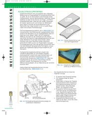
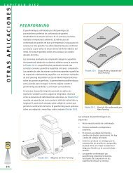
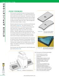
<strong>Metal</strong> <strong>Improvement</strong> <strong>Company</strong>, Inc. (MIC) is a wholly owned subsidiary of the Curtiss-Wright Corporation.<br />
Founded in 1946, MIC specializes in providing <strong>shot</strong> <strong>peening</strong> services to many industries as a means of<br />
preventing metal failures. MIC operates <strong>shot</strong> <strong>peening</strong> plants throughout North America and Western<br />
Europe with process licensees worldwide. Additionally, MIC operates a network of heat treating<br />
facilities and manufactures reed valves. A complete facility listing is printed on the back cover of this<br />
publication.<br />
Each MIC <strong>shot</strong> <strong>peening</strong> plant is capable of processing parts of diverse shapes, sizes and materials under<br />
rigidly controlled conditions. MIC develops the latest, state-of-the-art <strong>peening</strong> equipment based on the<br />
body of experience gathered over more than 50 years in the business.<br />
<strong>Metal</strong> <strong>Improvement</strong> <strong>Company</strong>, Inc. is the recognized leader in developing applications and controls used<br />
in <strong>shot</strong> <strong>peening</strong>. Shot Peening Applications – Eighth Edition replaces the Seventh Edition as the<br />
foremost engineering manual on the controlled <strong>shot</strong> <strong>peening</strong> process.<br />
MIC has available "Shot Peening Applications - The Video" which, especially when part of a live<br />
presentation by one of our Technical Service Managers, is the ideal medium for a company group or a<br />
meeting of a technical society. For more information you may contact the nearest MIC <strong>shot</strong> <strong>peening</strong><br />
facility (see back cover), our World Service Headquarters or visit our web site at<br />
www.metalimprovement.com. The Eighth Edition is also available in French, German, Spanish<br />
and Italian.<br />
MIC is pleased to share its experience and knowledge in the <strong>shot</strong> <strong>peening</strong> field so that engineers and<br />
metallurgists may be aware of the benefits of <strong>shot</strong> <strong>peening</strong>. Our Technical Service Managers are<br />
available to assist in the solution of many engineering problems that can be overcome by <strong>shot</strong> <strong>peening</strong>.<br />
Copyright © 2001<br />
By<br />
<strong>Metal</strong> <strong>Improvement</strong> <strong>Company</strong>, Inc.<br />
www.metalimprovement.com<br />
I N T R O D U C T I O N<br />
5
C H A P T E R O N E<br />
THEORY<br />
6<br />
T H E S H O T P E E N I N G<br />
P R O C E S S<br />
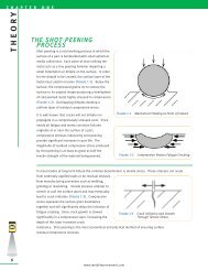
Shot <strong>peening</strong> is a cold working process in which the<br />
surface of a part is bombarded with small spherical<br />
media called <strong>shot</strong>. Each piece of <strong>shot</strong> striking the<br />
metal acts as a tiny <strong>peening</strong> hammer imparting a<br />
small indentation or dimple on the surface. In order<br />
for the dimple to be created, the surface layer of the<br />
metal must yield in tension (Figure 1-1). Below the<br />
surface, the compressed grains try to restore the<br />
surface to its original shape producing a hemisphere<br />
of cold-worked metal highly <strong>stress</strong>ed in compression<br />
(Figure 1-2). Overlapping dimples develop a<br />
uniform layer of <strong>residual</strong> compressive <strong>stress</strong>.<br />
It is well known that cracks will not initiate nor<br />
propagate in a compressively <strong>stress</strong>ed zone. Since<br />
nearly all fatigue and <strong>stress</strong> corrosion failures<br />
originate at or near the surface of a part,<br />
compressive <strong>stress</strong>es induced by <strong>shot</strong> <strong>peening</strong><br />
provide significant increases in part life. The<br />
magnitude of <strong>residual</strong> compressive <strong>stress</strong> produced<br />
by <strong>shot</strong> <strong>peening</strong> is at least as great as half the<br />
tensile strength of the material being peened.<br />
In most modes of long term failure the common denominator is tensile <strong>stress</strong>. These <strong>stress</strong>es can result<br />
from externally applied loads or be <strong>residual</strong> <strong>stress</strong>es<br />
from manufacturing processes such as welding,<br />
grinding or machining. Tensile <strong>stress</strong>es attempt to<br />
stretch or pull the surface apart and may eventually<br />
lead to crack initiation (Figure 1-3). Compressive<br />
<strong>stress</strong> squeezes the surface grain boundaries<br />
together and will significantly delay the initiation of<br />
fatigue cracking. Since crack growth is slowed<br />
Figure 1-3 Crack Initiation and Growth<br />
significantly in a compressive layer, increasing the<br />
Through Tensile Stress<br />
depth of this layer increases crack<br />
resistance. Shot <strong>peening</strong> is the most economical and practical method of ensuring surface<br />
<strong>residual</strong> compressive <strong>stress</strong>es.<br />
www.metalimprovement.com<br />
Figure 1-1 Mechanical Yielding at Point of Impact<br />
Figure 1-2 Compression Resists Fatigue Cracking
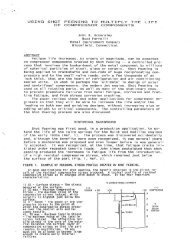
Shot <strong>peening</strong> is primarily used to combat metal fatigue. The following points pertain to metal fatigue and<br />
its application to the Typical Stress versus Load Cycles graph shown in Figure 1-4.<br />
• Fatigue loading<br />
consists of tens of<br />
thousands to millions<br />
of repetitive load<br />
cycles. The loads<br />
create applied tensile<br />
<strong>stress</strong> that attempt to<br />
stretch/pull the<br />
surface of the<br />
material apart.<br />
• A linear reduction in<br />
tensile <strong>stress</strong> results<br />
in an exponential<br />
increase in fatigue life<br />
(Number of Load<br />
Cycles). The graph<br />
(Figure 1-4) shows<br />
that a 38 ksi (262<br />
MPa) reduction in<br />
<strong>stress</strong> (32%) results in<br />
Figure 1-4 Typical Stress vs Load Cycles<br />
a 150,000 cycle life increase (300%).<br />
S H O T P E E N I N G<br />
R E S I D U A L<br />
S T R E S S<br />
The <strong>residual</strong> <strong>stress</strong> generated by<br />
<strong>shot</strong> <strong>peening</strong> is of a compressive<br />
nature. This compressive <strong>stress</strong><br />
offsets or lowers applied tensile<br />
<strong>stress</strong>. Quite simply, less (tensile)<br />
<strong>stress</strong> equates to longer part life.<br />
A typical <strong>shot</strong> <strong>peening</strong> <strong>stress</strong> profile<br />
is depicted in Figure 1-5.<br />
Maximum Compressive Stress –<br />
This is the maximum value of<br />
compressive <strong>stress</strong> induced. It is<br />
normally just below the surface.<br />
As the magnitude of the maximum<br />
Figure 1-5 Typical Shot Peening Residual Stress Profile<br />
compressive <strong>stress</strong> increases so does the resistance to fatigue cracking.<br />
Depth of Compressive Layer – This is the depth of the compressive layer resisting crack growth. The layer<br />
depth can be increased by increasing the <strong>peening</strong> impact energy. A deeper layer is generally desired for<br />
crack growth resistance.<br />
Surface Stress – This magnitude is usually less than the Maximum Compressive Stress.<br />
www.metalimprovement.com<br />
C H A P T E R O N E<br />
THEORY<br />
7
C H A P T E R O N E<br />
THEORY<br />
8<br />
SUMMATION OF APPLIED<br />
AND RESIDUAL STRESS<br />
When a component is <strong>shot</strong> peened and subjected to<br />
an applied load, the surface of the component<br />
experiences the net <strong>stress</strong> from the applied load and<br />
<strong>shot</strong> <strong>peening</strong> <strong>residual</strong> <strong>stress</strong>. Figure 1-6 depicts a<br />
bar with a three-point load that creates a bending<br />
<strong>stress</strong> at the surface.<br />
The diagonal dashed line is the tensile <strong>stress</strong> created<br />
from the bending load. The curved dashed line is the<br />
(<strong>residual</strong>) compressive <strong>stress</strong> from <strong>shot</strong> <strong>peening</strong>.<br />
The solid line is the summation of the two showing a<br />
significant reduction of tensile <strong>stress</strong> at the surface.<br />
Shot <strong>peening</strong> is highly advantageous for the following two conditions.<br />
• Stress risers • High strength materials<br />
Stress risers may consist of radii, notches, cross holes, grooves, keyways, etc… Shot <strong>peening</strong> induces a<br />
high magnitude, localized compressive <strong>stress</strong> to offset the <strong>stress</strong> concentration factor created from these<br />
geometric changes.<br />
Shot <strong>peening</strong> is ideal for high strength materials. Compressive <strong>stress</strong> is directly correlated to a material’s<br />
tensile strength. The higher the tensile strength, the more compressive <strong>stress</strong> that can be induced. Higher<br />
strength materials have a more rigid crystal structure. This crystal lattice can withstand greater degrees of<br />
strain and consequently can store more <strong>residual</strong> <strong>stress</strong>.<br />
A p p l i c a t i o n C a s e S t u d y<br />
NASA LANGLEY CRACK GROWTH STUDY<br />
Engineers at NASA performed a study on crack growth rates of 2024-T3 aluminum with and without <strong>shot</strong><br />
<strong>peening</strong>. The samples were tested with an initial crack of 0.050" (1.27 mm) and then cycle tested to failure. It<br />
should be noted that the United States Air Force damage tolerance rogue flaw is 0.050" (1.27 mm).<br />
It was found that crack growth was significantly delayed when <strong>shot</strong> <strong>peening</strong> was included. As the following<br />
results demonstrate, at a 15 ksi (104 MPa) net <strong>stress</strong> condition the remaining life increased by 237%. At a 20<br />
ksi (138 MPa) net <strong>stress</strong> condition the remaining life increased by 81%.<br />
This test reflects conditions that are harsher than real world conditions. Real world conditions would generally<br />
not have initial flaws and should respond with better fatigue life improvements at these <strong>stress</strong> levels.<br />
NON-SHOT PEENED TEST RESULTS<br />
Net Number Average<br />
Stress Of Tests Life Cycles<br />
15 ksi 2 75,017<br />
20 3 26,029<br />
Note on sample preparation: A notch was placed in the surface via the EDM process. The samples were loaded<br />
in fatigue until the crack grew to ~ 0.050" (1.27 mm). If samples were <strong>shot</strong> peened, they were peened after the<br />
initial crack of 0.050" (1.27 mm) was generated. This was the starting point for the above results. [Ref 1.1]<br />
www.metalimprovement.com<br />
Figure 1-6 Resultant Stress in a Shot Peened<br />
Beam with an External Load Applied<br />
SHOT PEENED TEST RESULTS<br />
Net Number Average Percent<br />
Stress Of Tests Life Cycles Increase<br />
15 ksi 2 253,142 237%<br />
20 3 47,177 81%
D E P T H O F R E S I D U A L<br />
S T R E S S<br />
The depth of the compressive layer is influenced by<br />
variations in <strong>peening</strong> parameters and material<br />
hardness [Ref 1.2]. Figure 1-7 shows the relationship<br />
between the depth of the compressive layer and the<br />
<strong>shot</strong> <strong>peening</strong> intensity for five materials: steel 31 HRC,<br />
steel 52 HRC, steel 60 HRC, 2024 aluminum and<br />
titanium 6Al-4V. Depths for materials with other<br />
hardness values can be interpolated.<br />
S H O T P E E N I N G M E D I A<br />
Media used for <strong>shot</strong> <strong>peening</strong> (see also Chapter 12)<br />
consists of small spheres of cast steel, conditioned<br />
cut wire (both carbon and stainless steel), ceramic or<br />
glass materials. Most often cast or wrought carbon<br />
steel is employed. Stainless steel media is used in<br />
Figure 1-7 Depth of Compression<br />
vs. Almen Arc Height<br />
applications where iron contamination on the part surface is of concern.<br />
Carbon steel cut wire, conditioned into near round<br />
shapes, is being specified more frequently due to its<br />
uniform, wrought consistency and great durability. It<br />
is available in various grades of hardness and in much<br />
tighter size ranges than cast steel <strong>shot</strong>.<br />
Glass beads are also used where iron contamination is<br />
of concern. They are generally smaller and lighter<br />
than other media and can be used to peen into sharp<br />
radii of threads and delicate parts where very low<br />
intensities are required.<br />
EFFECT O F S H OT<br />
HARDNESS<br />
It has been found that the hardness of the <strong>shot</strong> will<br />
influence the magnitude of compressive <strong>stress</strong><br />
(Figure 1-8). The <strong>peening</strong> media should be at least as<br />
hard or harder than the parts being peened unless<br />
Figure 1-8 Peening 1045 Steel (Rc 50+) [Ref 1.3]<br />
surface finish is a critical factor. For a large number of both ferrous and nonferrous parts, this criterion is<br />
met with regular hardness steel <strong>shot</strong> (45-52 HRC).<br />
The increased use of high strength, high hardness steels (50 HRC and above) is reflected in the use of<br />
special hardness <strong>shot</strong> (55-62 HRC).<br />
REFERENCES:<br />
1.1 Dubberly, Everett, Matthews, Prabhakaran, Newman; The Effects of Shot and Laser Peening on Crack Growth and Fatigue Life in 2024<br />
Aluminum Alloy and 4340 Steel, US Air Force Structural Integrity Conference, 2000<br />
1.2 Fuchs; Shot Peening Stress Profiles<br />
1.3 Lauchner, WESTEC Presentation March 1974, Northrup Corporation; Hawthorne, California<br />
www.metalimprovement.com<br />
C H A P T E R O N E<br />
THEORY<br />
9
C H A P T E R T W O<br />
RESPONSE OF METALS<br />
10<br />
H I G H S T R E N G T H S T E E L S<br />
The <strong>residual</strong> compressive <strong>stress</strong> induced by <strong>shot</strong> <strong>peening</strong> is a percentage of the ultimate tensile strength<br />
and this percentage increases as the strength/hardness increases. Higher strength/hardness metals<br />
tend to be brittle and sensitive to surface notches. These conditions can be overcome by <strong>shot</strong> <strong>peening</strong><br />
permitting the use of<br />
high strength metals in<br />
fatigue prone<br />
applications. Aircraft<br />
landing gear are often<br />
designed to strength<br />
levels of 300 ksi (2068<br />
MPa) that incorporate<br />
<strong>shot</strong> <strong>peening</strong>. Figure 2-<br />
1 shows the relationship<br />
between <strong>shot</strong> <strong>peening</strong><br />
and use of higher<br />
strength materials.<br />
Without <strong>shot</strong> <strong>peening</strong>,<br />
optimal fatigue<br />
Figure 2-1 Fatigue Strength vs. Ultimate Tensile Strength<br />
properties for machined<br />
steel components are obtained at approximately 30 HRC. At higher strength/hardness levels, materials<br />
lose fatigue strength due to increased notch sensitivity and brittleness. With the addition of compressive<br />
<strong>stress</strong>es, fatigue strength increases proportionately to increasing strength/hardness. At 52 HRC, the<br />
fatigue strength of the <strong>shot</strong> peened specimen is 144 ksi (993 MPa), more than twice the fatigue strength<br />
of the unpeened, smooth specimen [Ref 2.1].<br />
Typical applications that take advantage of high strength/hardness and excellent fatigue properties with<br />
<strong>shot</strong> <strong>peening</strong> are impact wrenches and percussion tools. In addition, the fatigue strength of peened<br />
parts is not impaired by shallow scratches that could otherwise be detrimental to unpeened high<br />
strength steel [Ref 2.2].<br />
www.metalimprovement.com
C A R B U R I Z E D S T E E L S<br />
Carburizing and carbonitriding are heat treatment processes that result in very hard surfaces. They are<br />
commonly 55-62 HRC. The benefits of <strong>shot</strong> <strong>peening</strong> carburized steels are as follows:<br />
• High magnitudes of compressive <strong>stress</strong> of ~ 200 ksi (1379 MPa) or greater offer<br />
excellent fatigue benefits<br />
• Carburizing anomalies resulting from surface intergranular oxidation are reduced.<br />
Shot hardness of 55-62 HRC is recommended for fully carburized and carbonitrided parts if maximum<br />
fatigue properties are desired.<br />
A p p l i c a t i o n C a s e S t u d y<br />
HIGH PERFORMANCE CRANKSHAFTS<br />
Crankshafts for 4-cylinder<br />
high performance engines<br />
were failing prematurely<br />
after a few hours running on<br />
test at peak engine loads.<br />
Testing proved that gas<br />
carburizing and <strong>shot</strong> <strong>peening</strong><br />
the crankpins gave the best<br />
fatigue performance (Figure<br />
2-2). Results from nitriding<br />
and <strong>shot</strong> <strong>peening</strong> also<br />
demonstrated favorable<br />
results over the alternative<br />
to increase the crankpin<br />
diameter [Ref 2.3].<br />
Figure 2-2 Comparison of Shot Peened<br />
Nitrided & Gas Carburized Crank Pins<br />
D E C A R B U R I Z A T I O N<br />
Decarburization is the reduction in surface carbon content of a ferrous alloy during thermal processing.<br />
It has been shown that decarburization can reduce the fatigue strength of high strength steels (240 ksi,<br />
1650 MPa or above) by 70-80% and lower strength steels (140-150 ksi, 965-1030 MPa) by 45-55%<br />
[Refs 2.4, 2.5 and 2.6].<br />
Decarburization is a surface phenomenon not particularly related to depth. A depth of 0.003 inch<br />
decarburization can be as detrimental to fatigue strength as a depth of 0.030 inch [Refs 2.4, 2.5 and 2.6].<br />
www.metalimprovement.com<br />
C H A P T E R T W O<br />
RESPONSE OF METALS<br />
11
C H A P T E R T W O<br />
RESPONSE OF METALS<br />
12<br />
Shot <strong>peening</strong> has proven to be effective in restoring most of the fatigue strength lost due to decarburization<br />
[Ref 2.7]. Because the decarburized layer is not easily detectable on quantities of parts, <strong>peening</strong> can<br />
insure the integrity of the parts if decarburization is suspected. If a gear that is intended to have a high<br />
surface hardness (58+ HRC) exhibits unusually heavy dimpling after <strong>peening</strong>, decarburization should<br />
be suspected.<br />
Decarburization is often accompanied with the undesirable metallurgical condition of retained austenite.<br />
By cold working the surface, <strong>shot</strong> <strong>peening</strong> reduces the percentage of retained austenite.<br />
A p p l i c a t i o n C a s e S t u d y<br />
REDUCTION OF RETAINED AUSTENITE - 5120 CARBURIZED STEEL,<br />
SHOT PEENED AT 0.014" (0.36 mm) A INTENSITY<br />
Retained Austenite<br />
(Volume %)<br />
Depth (inches) Depth (mm) Unpeened Peened<br />
0.0000 0.00 5 3<br />
0.0004 0.01 7 4<br />
0.0008 0.02 14 5<br />
0.0012 0.03 13 6<br />
0.0016 0.04 14 7<br />
0.0020 0.05 14 7<br />
0.0024 0.06 15 8<br />
0.0028 0.07 15 9<br />
0.0039 0.10 15 10<br />
0.0055 0.14 12 10<br />
[Ref 2.8]<br />
A U S T E M P E R E D D U C T I L E I R O N<br />
<strong>Improvement</strong>s in austempered ductile iron (ADI) have allowed it to replace steel forgings, castings, and<br />
weldments in some engineering applications. ADI has a high strength-to-weight ratio and the benefit of<br />
excellent wear capabilities. ADI has also replaced aluminum in certain high strength applications as it is at<br />
least 3 times stronger and only 2.5 times more dense. With the addition of <strong>shot</strong> <strong>peening</strong>, the allowable<br />
bending fatigue strength of ADI can be increased up to 75%. This makes certain grades of ADI with <strong>shot</strong><br />
<strong>peening</strong> comparable to case-carburized steels for gearing applications [Ref 2.9].<br />
C A S T I R O N<br />
There has been an increased demand in recent years for nodular cast iron components that are capable of<br />
withstanding relatively high fatigue loading. Cast iron components are often used without machining in<br />
applications where the cast surface is subject to load <strong>stress</strong>es. The presence of imperfections at casting<br />
surfaces in the form of pinholes, dross or flake graphite can considerably reduce the fatigue properties of<br />
unmachined pearlitic nodular irons. The unnotched fatigue limit may be reduced by as much as 40%,<br />
depending on the severity of the imperfections at the casting surface.<br />
www.metalimprovement.com
Shot <strong>peening</strong> can significantly improve properties when small cast-surface imperfections are present. One<br />
application is diesel engine cylinder liners. At the highest <strong>shot</strong> <strong>peening</strong> intensity used in the tests, the<br />
fatigue limit was 6% below that of fully machined fatigue specimens. This compares to a reduction of 20%<br />
for specimens in the as-cast unpeened condition. Visually, the <strong>peening</strong> on the as-cast surface has a<br />
polishing effect leaving the appearance of smoothing the rougher as-cast surface [Ref 2.10].<br />
A L U M I N U M A L L O Y S<br />
Traditional high strength aluminum alloys (series 2000 & 7000) have been used for decades in the aircraft<br />
industry because of their high strength-to-weight ratio. The following aluminum alloys have emerged with<br />
increasing use in critical aircraft/aerospace applications and respond equally well to <strong>shot</strong> <strong>peening</strong>:<br />
• Aluminum Lithium Alloys (Al-Li)<br />
• Isotropic <strong>Metal</strong> Matrix Composites (MMC)<br />
• Cast Aluminum (Al-Si)<br />
A p p l i c a t i o n C a s e S t u d y<br />
Al 7050-T7651 HIGH STRENGTH ALUMINUM<br />
Fatigue specimens were<br />
prepared from high strength<br />
Al 7050-T7651. All four sides<br />
of the center test portion<br />
were <strong>shot</strong> peened. Fatigue<br />
tests were conducted under<br />
a four-point reversed<br />
bending mode (R = -1). The<br />
S-N curve of the <strong>shot</strong> peened<br />
versus non-<strong>shot</strong> peened<br />
alloy is shown in Figure 2-3.<br />
It was found that <strong>shot</strong><br />
<strong>peening</strong> improved the<br />
fatigue endurance limit by<br />
Figure 2-3 S-N Curves for Shot Peened<br />
approximately 33%. Even in<br />
a regime where the <strong>stress</strong><br />
Aluminum Alloy 7050-T7651<br />
ratio is between the yield strength and the endurance limit, the fatigue strength increased by a factor of<br />
2.5 to almost 4 [Ref 2.11].<br />
www.metalimprovement.com<br />
C H A P T E R T W O<br />
RESPONSE OF METALS<br />
13
C H A P T E R T W O<br />
RESPONSE OF METALS<br />
14<br />
T I T A N I U M<br />
High Cycle Fatigue (HCF) - HCF of<br />
titanium is illustrated by Figure 2-4 that<br />
compares the capabilities of titanium<br />
alloy connecting rods for a high<br />
performance European sports car. The<br />
rods are manufactured using various<br />
processes. With <strong>shot</strong> <strong>peening</strong>, the<br />
fatigue limit was increased by<br />
approximately 20% while weight was<br />
reduced by some 40% as compared to<br />
steel connecting rods [Ref 2.12].<br />
Low Cycle Fatigue (LCF) - As is typical<br />
with other metals, the fatigue response<br />
with <strong>shot</strong> <strong>peening</strong> increases with<br />
higher cycle fatigue. Higher cycle<br />
fatigue would be associated with lower<br />
<strong>stress</strong>es whereas lower cycle fatigue<br />
would be associated with higher <strong>stress</strong><br />
levels. This is demonstrated<br />
graphically in the S-N Curve (Figure 1-4)<br />
and also Figure 2-5.<br />
Figure 2-5 shows the results of <strong>shot</strong><br />
<strong>peening</strong> titanium dovetail slots on a<br />
rotating engine component [Ref 2.13].<br />
There are two baseline load curves that<br />
are not <strong>shot</strong> peened. When <strong>shot</strong><br />
<strong>peening</strong> is applied, the base line curve<br />
that initially had more cycles to failure<br />
responded significantly better. Note<br />
that improvements in fatigue life are on<br />
an exponential basis.<br />
Figure 2-4 Comparison of Fatigue Strengths for Polished<br />
and Shot Peened Titanium Ti6A14V<br />
Figure 2-5 LCF Benefits from Shot Peening Notched Ti8-1-1<br />
The most common application of LCF for titanium is the rotating turbine engine hardware (discs, spools,<br />
& shafts) with the exception of blades. These components are <strong>shot</strong> peened to increase durability. Each<br />
takeoff and landing is considered one load cycle.<br />
M A G N E S I U M<br />
Magnesium alloys are not commonly used in fatigue applications. However, when used for the benefit of<br />
weight reduction, special <strong>peening</strong> techniques can be employed to achieve 25 - 35% improvement in<br />
fatigue strength.<br />
www.metalimprovement.com
P O W D E R M E T A L L U R G Y<br />
Optimized <strong>peening</strong> parameters have been shown to raise the endurance limit of sintered steel PM alloys by<br />
22% and the fatigue life by a factor of 10. [Ref. 2.14] Automotive components such as gears and connecting<br />
rods are candidates for PM with <strong>shot</strong> <strong>peening</strong>. Shot <strong>peening</strong> is most effective on higher density PM parts<br />
such as forged powder metal components.<br />
Surface densification by <strong>shot</strong> <strong>peening</strong> can increase the fatigue limit significantly, especially in the case of<br />
bending. The surface densification also assists in the closing of surface porosity of PM components for<br />
sealing and other engineering applications.<br />
Pressed and sintered ferrous powder materials are in increasing demand as the PM industry has grown into<br />
applications involving more highly <strong>stress</strong>ed components. Ancorsteel 1000B with 2% copper and 0.9%<br />
graphite had an endurance limit of 35 ksi (240 MPa) when tested without <strong>shot</strong> <strong>peening</strong>. Shot <strong>peening</strong> the<br />
test specimens increased the endurance limit 16% to 40.5 ksi (280 MPa) [Ref 2.16].<br />
REFERENCES:<br />
A p p l i c a t i o n C a s e S t u d y<br />
HIGH DENSITY POWDER METAL GEARS<br />
As part of a project sponsored by the German Federal Ministry of Education and Research, powdered metal<br />
alloys were tested for suitability in gearing applications. A MSP4.0Mo-0.1Nb powdered metal gear was<br />
tested against a reference machined 20MnCr5 case hardened steel. Tooth root load carrying capacity tests<br />
produced the following fatigue strength results (at 2 million load cycles). Note: the reference wrought<br />
steel’s fatigue strength was defined as 100%<br />
• Reference: Unpeened 20MnCr5 (wrought steel): 100%<br />
• Unpeened MSP4.0Mo-0.1Nb (powdered metal): 82%<br />
• Shot Peened MSP4.0Mo-0.1Nb (powdered metal): 109%<br />
The tests proved that the unpeened powdered metal had a fatigue strength 18% less than the wrought<br />
steel gear material. The <strong>shot</strong> peened powdered metal’s fatigue strength was 9% higher than the reference<br />
wrought steel [Ref 2.15].<br />
2.1 Horger; Mechanical and <strong>Metal</strong>lurgical Advantages of Shot Peening – Iron Age Reprint 1945<br />
2.2 Hatano and Namitki; Application of Hard Shot Peening to Automotive Transmission Gears, Special Steel Research Laboratory, Daido Steel<br />
<strong>Company</strong>, Ltd., Japan.<br />
2.3 Challenger; Comparison of Fatigue Performance Between Engine Crank Pins of Different Steel Types and Surface Treatments, Lucas Research<br />
Center, Solihull, England, July 1986<br />
2.4 Properties and Selection, <strong>Metal</strong>s Handbook, Eighth Edition, Vol. 1, pp. 223-224.<br />
2.5 Jackson and Pochapsky; The Effect of Composition on the Fatigue Strength of Decarburized Steel, Translations of the ASM, Vol. 39, pp. 45-60.<br />
2.6 Bush; Fatigue Test to Evaluate Effects of Shot Peening on High Heat Treat Steel - Lockheed Report No. 9761.<br />
2.7 Gassner; Decarburization and Its Evaluation by Chord Method, <strong>Metal</strong> Progress, March 1978, pp. 59-63.<br />
2.8 Internal <strong>Metal</strong> <strong>Improvement</strong> Co. Memo<br />
2.9 Keough, Brandenburg, Hayrynen; Austempered Gears and Shafts: Tough Solutions, Gear Technology March/April 2001, pp. 43-44.<br />
2.10 Palmer; The Effects of Shot Peening on the Fatigue Properties of Unmachined Pearlitic Nodular Graphite Iron Specimens Containing Small<br />
Cast Surface Imperfections, BCIRA Report #1658, The Casting Development Centre, Alvechurch, Birmingham, UK.<br />
2.11 Oshida and Daly; Fatigue Damage Evaluation of Shot Peened High Strength Aluminum Alloy, Dept. of Mechanical and Aerospace Engineering,<br />
Syracuse University, Syracuse, NY<br />
2.12 Technical Review, Progress in the Application of Shot-Peening Technology for Automotive Engine Components, Yamaha Motor Co., Ltd., 1998.<br />
2.13 McGann and Smith; Notch Low Cycle Fatigue Benefits from Shot Peening of Turbine Disk Slots.<br />
2.14 Sonsino, Schlieper, Muppman; How to Improve the Fatigue Properties of Sintered Steels by Combined Mechanical and Thermal Surface<br />
Treatments, Modern Developments in Powder <strong>Metal</strong>lurgy, Volume 15 - 17, 1985.<br />
2.15 Link, Kotthoff; Suitability of High Density Powder <strong>Metal</strong> Gears for Gear Applications; Gear Technology, January/February 2001.<br />
2.16 O’Brian; Impact and Fatigue Characterization of Selected Ferrous P/M Materials, Annual Powder <strong>Metal</strong>lurgy Conference, Dallas, TX. May 1987.<br />
www.metalimprovement.com<br />
C H A P T E R T W O<br />
RESPONSE OF METALS<br />
15
C H A P T E R T H R E E<br />
MANUFA CTURING PROCESSES<br />
16<br />
E F F E C T O N F A T I G U E L I F E<br />
Manufacturing processes have significant effects on fatigue properties of metal parts. The effects can be<br />
either detrimental or beneficial. Detrimental processes include welding, grinding, abusive machining, metal<br />
forming, etc… These processes leave the surface in <strong>residual</strong> tension. The summation of <strong>residual</strong> tensile<br />
<strong>stress</strong> and applied loading <strong>stress</strong> accelerates fatigue failure as shown in Figure 1-6.<br />
Beneficial manufacturing processes include surface hardening as it induces some <strong>residual</strong> compressive<br />
<strong>stress</strong> into the surface. Honing, polishing and burnishing are surface enhancing processes that remove<br />
defects and <strong>stress</strong> raisers from manufacturing operations. Surface rolling induces compressive <strong>stress</strong> but is<br />
primarily limited to cylindrical geometries. Shot <strong>peening</strong> has no geometry limitations and produces results<br />
that are usually the most economical.<br />
The effect of <strong>residual</strong> <strong>stress</strong> on fatigue life is demonstrated in the following example. A test by an airframe<br />
manufacturer on a wing fitting showed the initiation of a crack at just 60% of predicted life. The flaw was<br />
removed and the same area of the part <strong>shot</strong> peened. The fitting was then fatigue tested to over 300% life<br />
without further cracking even with reduced cross sectional thickness [Ref 3.1].<br />
W E L D I N G<br />
The <strong>residual</strong> tensile <strong>stress</strong> from welding is created because the weld consumable is applied in its molten state.<br />
This is its hottest, most expanded state. It then bonds to the base material, which is much cooler. The weld<br />
cools rapidly and attempts to shrink during the cooling. Since it has already bonded to the cooler, stronger<br />
base material it is unable to shrink. The net result is a weld that is essentially being "stretched" by the base<br />
material. The heat affected zone is usually most affected by the <strong>residual</strong> <strong>stress</strong> and hence where failure will<br />
usually occur. Inconsistency in the weld<br />
filler material, chemistry, weld geometry,<br />
porosity, etc… act as a <strong>stress</strong> risers for<br />
<strong>residual</strong> and applied tensile <strong>stress</strong> to<br />
initiate fatigue failure.<br />
As shown in Figure 3-1, <strong>shot</strong> <strong>peening</strong> is<br />
extremely beneficial in reversing the<br />
<strong>residual</strong> <strong>stress</strong> from welding that tends to<br />
cause failure in the heat affected zone<br />
from a tensile to a compressive state.<br />
Figure 3-1 demonstrates a number of<br />
interesting changes in <strong>residual</strong> <strong>stress</strong><br />
from welding, thermal <strong>stress</strong> relieving,<br />
and <strong>shot</strong> <strong>peening</strong> [Ref 3.2]. Tensile<br />
<strong>stress</strong>es generated from welding are<br />
Figure 3-1 Residual Stresses from Welding<br />
additive with applied load <strong>stress</strong>es. This combined <strong>stress</strong> will accelerate failure at welded connections.<br />
When the weld is <strong>stress</strong> relieved at 1150 °F (620 °C) for one hour, the tensile <strong>stress</strong> is reduced to almost zero.<br />
This reduction of tensile <strong>stress</strong> will result in improved fatigue properties.<br />
www.metalimprovement.com
If the weld is <strong>shot</strong> peened (rather than <strong>stress</strong> relieved) there is a significant reversal of <strong>residual</strong> <strong>stress</strong> from<br />
tensile to compressive. This will offer significant resistance to fatigue crack initiation and propagation.<br />
Figure 3-1 shows the optimal manufacturing sequence for welding is to <strong>stress</strong> relieve and then <strong>shot</strong><br />
peen. The <strong>stress</strong> relieving process softens the weld such that inducing a deeper layer of compressive<br />
<strong>stress</strong> becomes possible.<br />
A p p l i c a t i o n C a s e S t u d y<br />
FATIGUE OF OFFSHORE STEEL STRUCTURES<br />
A Norwegian research program<br />
concluded that the combination of Steel Condition<br />
Fatigue Strength<br />
At 1,000,000 Cycles<br />
weld toe grinding and <strong>shot</strong> <strong>peening</strong><br />
Base Material ~ 50 ksi (340 MPa)<br />
gave the largest improvement in<br />
Weld Toe Ground & Peened ~ 44 ksi (300 MPa)<br />
the structure life. This corresponds Weld Toe Ground (only) ~ 26 ksi (180MPa)<br />
to more than a 100% increase in<br />
the as-welded strength at one<br />
As Welded (only) ~ 20 ksi (140MPa)<br />
million cycles [Ref 3.3]. Other research shows that the improvement in weld fatigue strength from <strong>shot</strong><br />
<strong>peening</strong> increases in proportion to the yield strength of the parent metal.<br />
The American Welding Society (AWS) Handbook cautions readers to consider <strong>residual</strong> tensile <strong>stress</strong>es from<br />
welding if the fabrication is subject to fatigue loading as described in the following statement. "Localized<br />
<strong>stress</strong>es within a structure may result entirely from external loading, or there may be a combination of<br />
applied and <strong>residual</strong> <strong>stress</strong>es. Residual <strong>stress</strong>es are not cyclic, but they may augment or detract from<br />
applied <strong>stress</strong>es depending on their respective sign. For this reason, it may be advantageous to induce<br />
compressive <strong>residual</strong> <strong>stress</strong> in critical areas of the weldment where cyclic applied <strong>stress</strong>es are expected".<br />
The use of the <strong>shot</strong> <strong>peening</strong> process to improve resistance to fatigue as well as <strong>stress</strong> corrosion cracking in<br />
welded components is recognized by such organizations as:<br />
• American Society of Mechanical Engineers [Ref. 3.4]<br />
• American Bureau of Shipping [Ref. 3.5]<br />
• American Petroleum Institute [Ref. 3.6]<br />
• National Association of Corrosion Engineers [Ref. 3.7]<br />
A p p l i c a t i o n C a s e S t u d y<br />
TURBINE ENGINE HP COMPRESSOR ROTORS<br />
Two leading companies in the manufacture of jet turbine engines jointly manufacture high pressure<br />
compressor rotors. Separate pieces are machined from forged titanium (Ti 4Al-6V) and then welded<br />
together. Testing produced the following results:<br />
As Welded 4,000 cycles*<br />
Welded and polished 6,000 cycles<br />
Welded and peened 16,000 cycles<br />
www.metalimprovement.com<br />
* In aircraft engine terminology one cycle<br />
equals the ramp up required for one take-off of<br />
the aircraft for which the engine is configured.<br />
Initially, <strong>shot</strong> <strong>peening</strong> was used as additional "insurance" from failure. After many years of failure<br />
free service, coupled with innovations in <strong>shot</strong> <strong>peening</strong> controls, <strong>shot</strong> <strong>peening</strong> has been incorporated<br />
as a full manufacturing process in engine upgrades [Ref 3.8].<br />
C H A P T E R T H R E E<br />
MANUFA CTURING PROCESSES<br />
17
C H A P T E R T H R E E<br />
MANUFA CTURING PROCESSES<br />
18<br />
G R I N D I N G<br />
Typically, grinding induces <strong>residual</strong> tensile <strong>stress</strong><br />
as a result of localized heat generated during<br />
the process. The metal in contact with the<br />
abrasive medium heats locally and attempts to<br />
expand. The heated material is weaker than the<br />
surrounding metal and yields in compression.<br />
Upon cooling the yielded metal attempts to<br />
contract. This contraction is resisted by the<br />
surrounding metal resulting in <strong>residual</strong> tensile<br />
<strong>stress</strong>. Residual tensile <strong>stress</strong> of any magnitude<br />
will have a negative effect on fatigue life and<br />
resistance to <strong>stress</strong> corrosion cracking.<br />
Figure 3-2 graphically depicts <strong>residual</strong> tensile<br />
<strong>stress</strong> generated from various grinding processes [Ref 3.9]. A 1020, 150-180 BHN carbon steel (with and<br />
without weld) was ground abusively and conventionally. Figure 3-2 shows that the grinding processes<br />
resulted in high surface tension with the abusive grind having a deeper (detrimental) layer of <strong>residual</strong> tension.<br />
Shot <strong>peening</strong> after grinding will reverse the <strong>residual</strong> <strong>stress</strong> state from tensile to compressive. The beneficial<br />
<strong>stress</strong> reversal is similar to that from <strong>shot</strong> <strong>peening</strong> welded regions in a state of tension.<br />
Figure 3-3 Plating Micro-Cracks<br />
P L A T I N G<br />
Many parts are <strong>shot</strong> peened prior to chrome and electroless<br />
nickel plating to counteract the potential harmful effects on<br />
fatigue life. Fatigue deficits from plating may occur from the<br />
micro-cracking in the brittle surface, hydrogen embrittlement<br />
or <strong>residual</strong> tensile <strong>stress</strong>es.<br />
Figure 3-3 is a 1200x SEM photograph showing a network of<br />
very fine cracks that is typical of hard chrome plating [Ref 3.10].<br />
Under fatigue loading, the micro-cracks can propagate into the<br />
base metal and lead to fatigue failure.<br />
When the base metal is <strong>shot</strong> peened, the potential for fatigue<br />
crack propagation into the base metal from the plating is<br />
dramatically reduced. Figure 3-4 illustrates this concept and<br />
Figure 3-4 Compressive Stress Resists assumes dynamic loading on a component.<br />
Micro-Crack Growth<br />
The graphic on the left shows the micro-cracking propagating<br />
into the base material. When <strong>shot</strong> peened, the graphic on the right shows the compressive layer preventing<br />
the micro-cracking from propagating into the base material.<br />
Shot <strong>peening</strong> prior to plating is recommended on cyclically loaded parts to enhance fatigue properties. For<br />
parts that require unlimited life under dynamic loads, federal specifications QQ-C-320 and MIL-C-26074 call for<br />
<strong>shot</strong> <strong>peening</strong> of steel parts prior to chrome or electroless nickel-plating. Other hard plating processes such as<br />
electrolytic nickel may also lower fatigue strength.<br />
www.metalimprovement.com<br />
Figure 3-2 Residual Stresses from Grinding
A N O D I Z I N G<br />
Hard anodizing is another application in which <strong>shot</strong> <strong>peening</strong> improves fatigue resistance of coated<br />
materials. Benefits are similar to those for plating providing the <strong>peening</strong> is performed to the base<br />
material before anodizing.<br />
A p p l i c a t i o n C a s e S t u d y<br />
ANODIZED ALUMINUM RINGS<br />
Aluminum (AlZnMgCu 0.5) rings with external teeth were tested for comparison purposes with<br />
anodizing and <strong>shot</strong> <strong>peening</strong>. The rings had an outside diameter of ~ 24" (612 mm) and a tensile<br />
strength of ~ 71 ksi (490 MPa). The (hard) anodizing layer was ~ 0.0008" (0.02 mm) thick.<br />
Bending fatigue tests were<br />
conducted to find the load<br />
to cause a 10% failure<br />
probability at one million<br />
cycles. The following table<br />
shows the results [Ref 3.11].<br />
P L A S M A S P R A Y<br />
Plasma spray coatings are primarily used in applications that require excellent wear resistance. Shot<br />
<strong>peening</strong> has proven effective as a base material preparation prior to plasma spray applications that are<br />
used in cyclic fatigue applications. Shot <strong>peening</strong> has also been used after the plasma spray application to<br />
improve surface finish and close surface porosity.<br />
E L E C T R O - D I S C H A R G E M A C H I N I N G ( E D M )<br />
EDM is essentially a "force-free" spark erosion<br />
process. The heat generated to discharge<br />
molten metal results in a solidified recast layer<br />
on the base material. This layer can be brittle<br />
and exhibit tensile <strong>stress</strong>es similar to those<br />
generated during the welding process. Shot<br />
<strong>peening</strong> is beneficial in restoring the fatigue<br />
debits created by this process. In Figure 3-5<br />
the effect of <strong>shot</strong> <strong>peening</strong> on electro-chemical<br />
machined (ECM), electro-discharge machined<br />
(EDM) and electro-polished (ELP) surfaces is<br />
shown [Ref 3.12]. Figure 3-5 should be viewed<br />
in a clockwise format. ECM, EDM, & ELP<br />
fatigue strengths are compared with and<br />
without <strong>shot</strong> <strong>peening</strong>.<br />
Shot Peened Hard Anodized Load (10% Failure)<br />
No No 6744 lb / 30 KN<br />
Yes No 9218 lb / 41 KN<br />
No Yes 4496 lb / 20 KN<br />
Yes Yes 10,791 lb / 48 KN<br />
www.metalimprovement.com<br />
Figure 3-5 High Cycle Fatigue Behavior<br />
of Inconel 718<br />
C H A P T E R T H R E E<br />
MANUFA CTURING PROCESSES<br />
19
C H A P T E R T H R E E<br />
MANUFA CTURING PROCESSES<br />
20<br />
E L E C T R O - C H E M I C A L M A C H I N I N G ( E C M )<br />
Electro-chemical machining is the controlled dissolution of material by contact with a strong chemical<br />
reagent in the presence of an electric current. A reduction in fatigue properties is attributed to surface<br />
softening (the rebinder effect) and surface imperfections left by preferential attack on grain boundaries.<br />
A <strong>shot</strong> <strong>peening</strong> post treatment more than restores fatigue properties as shown in Figure 3-5 [Ref 3.12].<br />
A p p l i c a t i o n C a s e S t u d y<br />
DIAPHRAGM COUPLINGS<br />
<strong>Metal</strong> diaphragm couplings are often used in turbo-machinery applications. These couplings accommodate<br />
system misalignment through flexing. This flexing, or cyclic loading, poses concerns for fatigue failures.<br />
Researchers concluded that the ECM process produces parts that are geometrically near-perfect. However,<br />
they found under scanning electron microscope observation that small cavities sometimes developed on<br />
the surface as a result of ECM. These cavities apparently generated <strong>stress</strong> concentrations that lead to<br />
premature failures. Shot <strong>peening</strong> after ECM was able to overcome this deficiency and has significantly<br />
improved the endurance limit of the diaphragm couplings [Ref 3.13 & 3.14].<br />
REFERENCES:<br />
3.1 Internal <strong>Metal</strong> <strong>Improvement</strong> Co. Memo<br />
3.2 Molzen, Hornbach; Evaluation of Welding Residual Stress Levels Through Shot Peening and Heat Treating, AWS Basic Cracking<br />
Conference; Milwaukee, WI; July 2000<br />
3.3 Haagensen; Prediction of the <strong>Improvement</strong> in Fatigue Life of Welded Joints Due to Grinding, TIG Dressing, Weld Shape Control and Shot<br />
<strong>peening</strong>." The Norwegian Institute of Technology, Trondheim, Norway.<br />
3.4 McCulloch; American Society of Mechanical Engineers, Letter to H. Kolin, May 1975.<br />
3.5 Stern; American Bureau of Shipping, Letter to G. Nachman, July 1983.<br />
3.6 Ubben; American Petroleum Institute, Letter to G. Nachman, February 1967.<br />
3.7 N.A.C.E Standard MR-01-75, Sulfide Stress Cracking Resistant <strong>Metal</strong>lic Material for Oilfield Equipment, National Association of Corrosion Engineers.<br />
3.8 Internal <strong>Metal</strong> <strong>Improvement</strong> Co. Memo<br />
3.9 Molzen, Hornbach; Evaluation of Welding Residual Stress Levels Through Shot Peening and Heat Treating, AWS Basic Cracking Conference;<br />
Milwaukee, WI; July 2000<br />
3.10 <strong>Metal</strong>lurgical Associates, Inc; "Minutes" Vol.5 No.1, Winter 1999; Milwaukee, WI<br />
3.11 Internal <strong>Metal</strong> <strong>Improvement</strong> Co. Memo<br />
3.12 Koster, W.P., Observation on Surface Residual Stress vs. Fatigue Strength, Metcut Research Associates, Inc., Cincinnati, Ohio.<br />
Bulletin 677-1, June 1977<br />
3.13 Calistrat; <strong>Metal</strong> Diaphragm Coupling Performance, Hydrocarbon Processing, March 1977<br />
3.14 Calistrat; <strong>Metal</strong> Diaphragm Coupling Performance, 5th Turbomachinery Symposium, Texas A&M University, October 1976<br />
www.metalimprovement.com
B E N D I N G<br />
F A T I G U E<br />
Bending fatigue is the most<br />
common fatigue failure mode. This<br />
failure mode responds well to <strong>shot</strong><br />
<strong>peening</strong> because the highest<br />
(tensile) <strong>stress</strong> is at the surface.<br />
Figure 4-1 shows a cantilever beam<br />
under an applied bending load.<br />
The beams deflection causes the<br />
top surface to stretch putting it in a<br />
state of tension. Any radii or<br />
geometry changes along the top<br />
surface would act as <strong>stress</strong> risers.<br />
Figure 4-1 Highest Stress at Surface<br />
Fully reversed bending involves components that cycle through tensile and compressive load cycles. This<br />
is the most destructive type of fatigue loading. Fatigue cracks are initiated and propagated from the<br />
tensile portion of the load cycle.<br />
G E A R S<br />
Shot <strong>peening</strong> of gears is a very common application. Gears of any<br />
size or design are mainly <strong>shot</strong> peened to improve bending fatigue<br />
properties in the root sections of the tooth profile. The meshing of<br />
gear teeth is similar to the cantilever beam example. The load<br />
created from the tooth contact creates a bending <strong>stress</strong> in the root<br />
area below the point of contact (Figure 4-3).<br />
Figure 4-2 Ring & Pinion<br />
Gears are frequently <strong>shot</strong> peened after through hardening or surface<br />
hardening.<br />
Gear Assembly<br />
Increased<br />
surface<br />
hardness results in proportional increases in<br />
compressive <strong>stress</strong>. Maximum <strong>residual</strong><br />
compression from carburized and <strong>shot</strong> peened<br />
gears can range from 170-230 ksi (1170-1600<br />
MPa) depending on the carburizing treatment<br />
and <strong>shot</strong> <strong>peening</strong> parameters (Figure 4-4). It is<br />
common to use hard <strong>shot</strong> (55-62 HRC) when<br />
<strong>shot</strong> <strong>peening</strong> carburized gears. However,<br />
reduced hardness <strong>shot</strong> (45-52 HRC) may be<br />
used when carburized surfaces require less<br />
Figure 4-3 Polarized View of Applied Gear Stresses<br />
www.metalimprovement.com<br />
C H A P T E R F O U R<br />
BENDING FA T IGUE<br />
21
C H A P T E R F O U R<br />
BENDING FA T IGUE<br />
22<br />
disruption of the tooth flank surface.<br />
The amount of compressive <strong>stress</strong> will<br />
be ~ 50% of that which hard <strong>shot</strong> will<br />
induce.<br />
The optimal way to induce resistance<br />
to pitting fatigue near the gear tooth<br />
pitch line is to induce a compressive<br />
<strong>stress</strong> followed by a lapping, honing, or<br />
isotropic finishing process. Care must<br />
be taken to not remove more than 10%<br />
of the <strong>shot</strong> <strong>peening</strong> layer. Processes<br />
that refine the surface finish of <strong>shot</strong><br />
<strong>peening</strong> dimples allow the contact load<br />
Figure 4-4 Typical Carburized Gear Residual Stress Profile<br />
to be distributed over a larger surface area reducing contact <strong>stress</strong>es.<br />
<strong>Metal</strong> <strong>Improvement</strong> Co. offers a <strong>shot</strong> <strong>peening</strong> and superfinishing process called C.A.S.E. SM that has increased<br />
pitting fatigue resistance of gears by 500%. Please see Chapter 11 for additional information and photomicrographs<br />
on this process.<br />
Increases in fatigue strength of 30% or more at 1,000,000 cycles are common in certain gearing<br />
applications. The following organizations/specifications allow for increases in tooth bending loads when<br />
controlled <strong>shot</strong> <strong>peening</strong> is implemented.<br />
• Lloyds Register of Shipping: 20% increase [Ref 4.2]<br />
• Det Norske Veritas: 20% increase [Ref 4.3]<br />
• ANSI/AGMA 6032-A94 Marine Gearing Specification: 15% increase<br />
C O N N E C T I N G R O D S<br />
Connecting rods are excellent examples of<br />
metal components subjected to fatigue<br />
loading as each engine revolution results<br />
in a load cycle. The critical failure areas<br />
on most connecting rods are the radii on<br />
either side of the I-beams next to the<br />
large bore. Figure 4-5 shows a finite<br />
element <strong>stress</strong> analysis plot with the<br />
maximum <strong>stress</strong> areas shown in red.<br />
The most economical method of <strong>shot</strong><br />
<strong>peening</strong> is to peen the as-forged, as-cast<br />
or powdered metal rod prior to any<br />
Figure 4-5 Finite Element Stress Plot of a Connecting Rod<br />
machining of the bores or faces. This eliminates masking operations that will add cost. Rougher<br />
surfaces in compression have better fatigue properties than smooth surfaces in tension (or without<br />
<strong>residual</strong> <strong>stress</strong>) such that most peened surfaces do not require prior preparation or post operations.<br />
www.metalimprovement.com
C R A N K S H A F T S<br />
In most cases, all radii on a crankshaft are <strong>shot</strong> peened. These<br />
include the main bearing journals and crankpin radii as shown in<br />
Figure 4-6. The most highly <strong>stress</strong>ed area of a crankshaft is the<br />
crank pin bearing fillet. The maximum <strong>stress</strong> area is the bottom<br />
side of the pin fillet when the engine fires as the pin is in the top<br />
dead center position (Figure 4-6). It is common for fatigue<br />
cracks to initiate in this pin fillet and propagate through the web<br />
of the crankshaft to the adjacent main bearing fillet causing<br />
catastrophic failure.<br />
Experience has shown <strong>shot</strong> <strong>peening</strong> to be effective on forged steel,<br />
cast steel, nodular iron, and austempered ductile iron crankshafts. Fatigue strength increases of 10 to 30% are<br />
allowed by Norway’s Det Norske Veritas providing fillets are <strong>shot</strong> peened under controlled conditions [Ref 4.5].<br />
A p p l i c a t i o n C a s e S t u d y<br />
DIESEL ENGINE CRANKSHAFTS<br />
REFERENCES:<br />
4.1 Figure 4-2, Unigraphics Solutions, Inc. website (www.ugsolutions / www.solid-edge.com), June 2000<br />
4.2 Letter to W.C. Classon, Lloyds Register of Shipping, May 1990<br />
4.3 Sandberg; Letter to <strong>Metal</strong> improvement <strong>Company</strong>, Det Norske Veritas, September 1983<br />
4.4 Figure 4-5, Unigraphics Solutions, Inc. website (www.ugsolutions / www.solid-edge.com), June 2000<br />
4.5 Sandberg; Letter to <strong>Metal</strong> improvement <strong>Company</strong>, Det Norske Veritas, September 1983<br />
4.6 Internal <strong>Metal</strong> <strong>Improvement</strong> Co. Memo<br />
4.7 FAA Issues AD on TFE73, Aviation week & Space Technology; April 22, 1991<br />
www.metalimprovement.com<br />
Figure 4-6 Crankshaft Schematic<br />
Four point bending fatigue tests were carried out on test pieces from a diesel engine crankshaft. The<br />
material was Armco 17-10 Ph stainless steel. The required service of this crankshaft had to exceed one<br />
hundred million cycles. Fatigue strength of unpeened and <strong>shot</strong> peened test pieces were measured at one<br />
billion cycles. The fatigue strength for the unpeened material was 43 ksi (293 MPa) versus 56 ksi (386<br />
MPa) for the peened material. This is an increase of ~ 30% [Ref 4.6].<br />
A p p l i c a t i o n C a s e S t u d y<br />
TURBINE ENGINE DISKS<br />
In 1991 the Federal Aviation Authority issued an<br />
airworthiness directive that required inspection for cracks<br />
in the low pressure fan disk. Over 5,000 engines were in<br />
use on business jets in the United States and Europe.<br />
The FAA required that engines that did not have lance<br />
(<strong>shot</strong>) <strong>peening</strong> following machining in the fan blade<br />
dovetail slot be inspected. Those engines having fan<br />
disks without lance <strong>peening</strong> were required to reduce<br />
service life from 10,000 to 4,100 cycles (takeoffs and<br />
landings). Disks that were reworked with lance <strong>peening</strong><br />
per AMS 2432 (Computer Monitored Shot Peening) prior<br />
Figure 4-7 Lance Peening of Fan Disk<br />
to 4,100 cycles were granted a 3,000 cycle extension [Ref 4.7]. A typical lance <strong>peening</strong> operation of a fan<br />
disk is shown in Figure 4-7. See also Chapter 11 Internal Surfaces & Bores.<br />
C H A P T E R F O U R<br />
BENDING FA T IGUE<br />
23
C H A P T E R F I V E<br />
T ORSIONAL F A T IGUE<br />
24<br />
T O R S I O N A L<br />
F A T I G U E<br />
Torsional fatigue is a failure mode that<br />
responds well to <strong>shot</strong> <strong>peening</strong> because<br />
the greatest (tensile) <strong>stress</strong> occurs at<br />
the surface. Torsional loading creates<br />
<strong>stress</strong>es in both the longitudinal and<br />
perpendicular directions such that the<br />
maximum tensile <strong>stress</strong> is 45° to<br />
longitudinal axis of the component.<br />
Figure 5-1 depicts a solid bar loaded in<br />
pure torsion with a crack depicting reversed torsional loading.<br />
Lower strength materials tend to fail from torsional fatigue in the shear plane perpendicular to the longitudinal<br />
axis. This is because they are weaker in shear than in tension. Higher strength materials tend to fail at 45° to<br />
the longitudinal axis because they are weaker in tension than in shear.<br />
Figure 5-2 Compression<br />
Spring Assembly<br />
The spring wire analyzed in Figure 5-3<br />
was a 0.25" (6.35 mm) diameter<br />
Chrome-Silicon material with an<br />
ultimate tensile strength (UTS) of 260<br />
ksi (1793 MPa). The <strong>residual</strong> tensile<br />
<strong>stress</strong> at the ID after coiling was ~ 70<br />
ksi (483 MPa) and is the primary<br />
reason for failure at 80,000 load<br />
cycles [Ref 5.2].<br />
Shot <strong>peening</strong> induced a reversal of<br />
<strong>residual</strong> <strong>stress</strong> to a maximum<br />
compressive <strong>stress</strong> of ~ 150 ksi (1035<br />
MPa). This is 60% of UTS of the wire<br />
and resulted in fatigue life in excess of<br />
500,000 load cycles without failure.<br />
C O M P R E S S I O N S P R I N G S<br />
Compression springs are subject to high cycle fatigue and are one of the<br />
more common <strong>shot</strong> <strong>peening</strong> applications. The spring wire twists<br />
allowing the spring to compress creating a torsional <strong>stress</strong>. In addition<br />
to operating in high cycle fatigue conditions, the coiling process induces<br />
detrimental tensile <strong>stress</strong> at the inner diameter (ID) of the spring.<br />
Figure 5-3 demonstrates the <strong>residual</strong> <strong>stress</strong> after coiling and <strong>shot</strong><br />
<strong>peening</strong>.<br />
www.metalimprovement.com<br />
Figure 5-1 Torsional Loading<br />
Figure 5-3 Coil Spring ID Residual Stress<br />
With and Without Shot Peen
It is quite common to perform a baking operation after <strong>shot</strong> <strong>peening</strong> of springs. The baking operation is<br />
used as a stabilizing process in the manufacture of springs and is used to offset a potential setting problem<br />
that may occur with some <strong>shot</strong> peened spring designs. The baking is approximately 400 °F (205 °C) for 30<br />
minutes for carbon steel springs and is below the <strong>stress</strong> relief temperature of the wire. Temperatures above<br />
450 °F (230 °C) will begin to relieve the beneficial <strong>residual</strong> <strong>stress</strong> from <strong>shot</strong> <strong>peening</strong>.<br />
Other spring designs respond equally well to <strong>shot</strong> <strong>peening</strong>. The fatigue failure will occur at the location<br />
of the highest combination of <strong>residual</strong> and applied tensile <strong>stress</strong>. Torsion springs will generally fail at the<br />
OD near the tangent of the tang. Extension springs will generally fail at the inner radius of the hook.<br />
Other potential spring designs that can benefit from <strong>shot</strong> <strong>peening</strong> are leaf springs, cantilever springs, flat<br />
springs, etc…<br />
D R I V E S H A F T S<br />
Shaft applications are used to transmit<br />
power from one location to another through<br />
the use of rotation. This creates a torsional<br />
load on the rotating member. Since most<br />
drive shafts are primary load bearing<br />
members, they make excellent <strong>shot</strong> <strong>peening</strong><br />
applications. As shown in Figure 5-4 typical<br />
Figure 5-4 Drive Shaft Schematic<br />
failure locations for drive shafts are splines, undercuts, radii, & keyways.<br />
T O R S I O N B A R S<br />
Torsion bars and anti-sway bars are structural members often used in suspensions and other related<br />
systems. The bars are used to maintain stability by resisting twisting motion. When used in systems<br />
subjected to repetitive loads such as vehicle suspensions, <strong>shot</strong> <strong>peening</strong> offers advantages of weight<br />
savings and extended service life.<br />
A p p l i c a t i o n C a s e S t u d y<br />
AUTOMOTIVE TORSION BARS<br />
The automotive industry has used hollow torsion bars as a means of weight savings. Shot <strong>peening</strong><br />
was performed on the outer diameter where the highest load <strong>stress</strong>es occur. On heavy duty<br />
applications (four wheel drive utility trucks, SUVs, etc…) cracks can also occur on the inner diameter<br />
(ID) which also experiences torsional loads.<br />
MIC is able to <strong>shot</strong> peen the ID using its lance <strong>shot</strong> <strong>peening</strong> methods. This provides necessary<br />
compressive <strong>stress</strong> throughout the torsion/anti-sway bar length.<br />
REFERENCES:<br />
5.1 Figure 5-2, Unigraphics Solutions, Inc. website (www.ugsolutions / www.solid-edge.com), June 2000<br />
5.2 Lanke, Hornbach, Breuer; Optimization of Spring Performance Through Understanding and Application of Residual Stress; Wisconsin Coil Spring<br />
Inc., Lambda Research, Inc., <strong>Metal</strong> <strong>Improvement</strong> Co. Inc.; 1999 Spring Manufacturer’s Institute Technical Symposium; Chicago, IL May 1999<br />
www.metalimprovement.com<br />
C H A P T E R F I V E<br />
T ORSIONAL F A T IGUE<br />
25
C H A P T E R S I X<br />
A X IAL F A T IGUE<br />
26<br />
A X I A L F A T I G U E<br />
Axial fatigue is less common than other (fatigue) failure mechanisms. A smooth test specimen with axial<br />
loading has uniform <strong>stress</strong> throughout its cross section. For this reason, fatigue results of smooth, axial<br />
loaded <strong>shot</strong> peened specimens often do not show significant improvements in fatigue life. This is unlike<br />
bending and torsion that have the highest applied <strong>stress</strong> at the surface.<br />
In most situations, pure axial loading is rare as it is normally accompanied by bending. Shot <strong>peening</strong> of<br />
axial loaded components is useful when there are geometry changes resulting in <strong>stress</strong> concentrations.<br />
Undercut grooves, tool marks, cross holes and radii are typical examples of potential failure initiation sites.<br />
A p p l i c a t i o n C a s e S t u d y<br />
TRAIN EMERGENCY BRAKE PIN<br />
Figure 6-1 is part of a hydraulic brake<br />
assembly used in a mass transit system.<br />
The undercut sections near the chamfered<br />
end were designed to fail in the event of<br />
axial overload. During the investigation of<br />
premature failures it was found that a<br />
bending load was also occurring. The<br />
Figure 6-1 Brake Pin Schematic<br />
combined axial and bending load when simulated in test caused fatigue failure between 150,000 –<br />
2,600,000 cycles. Shot <strong>peening</strong> was added to the brake pin and all test specimens exceeded 6,000,000<br />
cycles without failure [Ref 6.1].<br />
A p p l i c a t i o n C a s e S t u d y<br />
AUXILIARY POWER UNIT (APU) EXHAUST DUCTS<br />
This type of APU is used to provide power to aircraft when they are on the ground with the main<br />
engines turned off. The tubular exhaust ducts are a high temperature 8009 aluminum alloy welded in<br />
an end-to-end design.<br />
Tension-tension fatigue tests measured fatigue strength of 23 ksi (156 MPa) at 3000 cycles in the as<br />
welded condition. Glass bead <strong>peening</strong> of the welds resulted in a 13% fatigue strength improvement to<br />
26 ksi (180 MPa) [Ref 6.2].<br />
REFERENCES:<br />
6.1 RATP, Cetim; Saint Etienne, France, 1996<br />
6.2 Internal <strong>Metal</strong> <strong>Improvement</strong> Co. Memo<br />
www.metalimprovement.com
F R E T TING F A I L U R E<br />
Fretting occurs when two highly loaded members have a common<br />
surface at which rubbing and sliding take place. Relative<br />
movements of microscopic amplitude result in surface<br />
discoloration, pitting, and eventual fatigue. Fine abrasive oxides<br />
develop that further contribute to scoring of the surfaces. Other<br />
failure mechanisms, such as fretting corrosion and fretting wear,<br />
commonly accompany fretting failures.<br />
Shot <strong>peening</strong> has been used to prevent fretting and eventual<br />
fretting failures by texturing the surface with a non-directional<br />
finish. This results in surface hardening (of certain materials) and<br />
Figure 7-1 Turbine Engine<br />
Assembly<br />
a layer of compressive <strong>stress</strong>. The compressive layer prevents initiation and growth of fretting fatigue<br />
cracks from scoring marks as a result of fretting.<br />
Fretting fatigue can occur when a rotating component is press fit onto a shaft. Vibration or shifting loads<br />
may cause the asperities of the press fit to bond and tear. The exposed surfaces will oxidize producing the<br />
"rusty powder" appearance of fretted steel.<br />
A p p l i c a t i o n C a s e S t u d y<br />
TURBOMACHINERY BLADES & BUCKETS<br />
A very common fretting environment is the dovetail root of<br />
turbomachinery blades. Shot <strong>peening</strong> is commonly used<br />
to prevent fretting failures of these roots. As shown in<br />
Figure 7-2 the blade roots have the characteristic fir tree<br />
shape. The tight mating fit coupled with demanding loading<br />
conditions require that the surfaces be <strong>shot</strong> peened to<br />
prevent failure associated with fretting.<br />
Many turbine and compressor blade roots are <strong>shot</strong> peened<br />
as OEM parts and re-<strong>shot</strong> peened upon overhaul to restore<br />
fatigue debits otherwise lost to fretting. The discs or wheels<br />
that support the blades should also be peened.<br />
P I T T I N G<br />
Resistance to pitting fatigue is of primary concern for those who design gears and other components<br />
involved with rolling/sliding contact. Many gears are designed such that contact failure is the limiting<br />
factor in gear design. Though not desirable, pitting failures generally occur more gradually and with less<br />
catastrophic consequences than root bending failures.<br />
www.metalimprovement.com<br />
Figure 7-2 Turbine Blade and<br />
Disc Assembly<br />
C H A P T E R S E V E N<br />
C ONTA CT F AILURE<br />
27
C H A P T E R S E V E N<br />
C ONTA CT F AILURE<br />
28<br />
Pitting failures initiate due to Hertzian and sliding contact <strong>stress</strong>es near the pitch line. When asperities<br />
from mating surfaces make contact, the loading is a complex combination of Herzian and tensile<br />
<strong>stress</strong>es. With continued operation, a<br />
micro-crack may initiate. Crack growth<br />
will continue until the asperity<br />
separates itself leaving a "pit".<br />
A condition of mixed lubrication is very<br />
susceptible to pitting failure. This occurs<br />
when the lubricant film is not quite thick<br />
enough to separate the surfaces and<br />
actual contact occurs between the<br />
asperities. Figure 7-3 shows a gear<br />
flank and the mechanisms that cause<br />
pitting [Ref 7.2].<br />
Shot <strong>peening</strong> has been proven to be highly<br />
beneficial in combating pitting fatigue when<br />
followed by a surface finish improvement process. By removing the asperities left from <strong>shot</strong> <strong>peening</strong>, the<br />
contact area is distributed over a larger surface area. It is important when finishing the <strong>shot</strong> peened<br />
surface to not remove more than 10% of the compressive layer. Please see Chap 11 for photomicrographs of<br />
a <strong>shot</strong> peened and isotropically finished surface using the C.A.S.E. SM Figure 7-3 Pitting Failure Schematic<br />
process.<br />
G A L L I N G<br />
Galling is an advanced form of adhesive wear that can occur on materials in sliding contact with no or only<br />
boundary lubrication. In its early stages it is sometimes referred to as scuffing. The adhesive forces<br />
involved cause plastic deformation and cold welding of opposing asperities. There is usually detachment of<br />
metal particles and gross transfer of fragments between surfaces. When severe, seizure may occur.<br />
Shot <strong>peening</strong> can be beneficial for surfaces that gall particularly when the materials are capable of work<br />
hardening. The cold worked surface also contains dimples that act as lubricant reservoirs. The following<br />
materials have demonstrated positive response to galling with the assistance of <strong>shot</strong> <strong>peening</strong>: Inconel 718<br />
& 750, Monel K-500, and alloys of stainless steel, titanium, and aluminum.<br />
REFERENCES:<br />
7.1 Figure 7-1, Unigraphics Solutions, Inc. website (www.ugsolutions / www.solid-edge.com), June 2000<br />
7.2 Hahlbeck; Milwaukee Gear; Milwaukee, WI / Powertrain Engineers; Pewaukee, WI<br />
www.metalimprovement.com
C O R R O S ION F A I L U R E<br />
Tensile related corrosion failures can be derived from either static or cyclic tensile <strong>stress</strong>es. In both types of<br />
failures, environmental influences contribute to failure. Environments such as salt water and sour gas wells<br />
create metallurgical challenges. In most cases, these environments become more aggressive with<br />
increasing temperature.<br />
S T R E S S C ORROSION C R A C K ING<br />
Stress corrosion cracking (SCC) failure is most often<br />
associated with static tensile <strong>stress</strong>. The static<br />
<strong>stress</strong> can be from applied <strong>stress</strong> (such as a bolted<br />
flange) or <strong>residual</strong> <strong>stress</strong> from manufacturing<br />
processes (such as welding). For SCC to occur three<br />
factors must be present.<br />
• Tensile <strong>stress</strong><br />
• Susceptible material<br />
• Corrosive environment<br />
Figure 8-1 shows the <strong>stress</strong> corrosion triangle in which each leg must be present for SCC to occur.<br />
The compressive layer from <strong>shot</strong> <strong>peening</strong> removes the tensile <strong>stress</strong> leg of the SCC triangle. Without tensile<br />
<strong>stress</strong>, SCC failure is significantly retarded or prevented from ever occurring. The following is a partial list of<br />
alloys that are susceptible to SCC failure.<br />
• Austenitic stainless steels<br />
• Certain alloys (& tempers) of series<br />
2000 & 7000 aluminum<br />
• Certain nickel alloys<br />
• Certain high strength steels<br />
• Certain brasses<br />
Figure 8-2 depicts a SCC failure. In austenitic 300<br />
series stainless steel, the “river branching” pattern<br />
is unique to SCC and is often used in failure<br />
analysis for identification purposes of this<br />
material.<br />
Figure 8-1 Stress Corrosion Cracking Triangle<br />
Figure 8-2 Stress Corrosion Cracking Failure<br />
of 300 Series Stainless Steel<br />
www.metalimprovement.com<br />
C H A P T E R E I G H T<br />
C ORROSION FAILURE<br />
29
C H A P T E R E I G H T<br />
C ORROSION FAILURE<br />
30<br />
A p p l i c a t i o n C a s e S t u d y<br />
FABRICATION OF CHEMICAL HANDLING EQUIPMENT<br />
Shot <strong>peening</strong> has been utilized as a cost savings measure for construction of chemical handling<br />
equipment. In cases where ammonia or chloride based solutions were to be contained, a lower cost<br />
SCC susceptible material was selected with <strong>shot</strong> <strong>peening</strong> rather than a more expensive non-susceptible<br />
material. Even with the additional <strong>shot</strong> <strong>peening</strong> operation, construction costs were less than using the<br />
more expensive alloy.<br />
The following table demonstrates the effectiveness of <strong>shot</strong> <strong>peening</strong> in combating <strong>stress</strong> corrosion<br />
cracking for the following stainless steel alloys. A load <strong>stress</strong> equivalent to 70% of the materials yield<br />
strength was applied [Ref 8.2].<br />
Material Peened Test Life<br />
(yes/no) (hours)<br />
316 SS no 11.3<br />
316 SS yes 1000 N.F.<br />
318 SS no 3.3<br />
318 SS yes 1000 N.F.<br />
321 SS no 5.0<br />
321 SS yes 1000 N.F.<br />
N.F. = No Failure<br />
C O R R O S ION F A T I G U E<br />
Corrosion fatigue is failure of components in corrosive environments associated with cyclic loading. Fatigue<br />
strength can be reduced by 50% or more when susceptible alloys are used in corrosive environments.<br />
A p p l i c a t i o n C a s e S t u d y<br />
SULFIDE STRESS CRACKING<br />
Hydrogen sulfide (H 2 S) is a commonly encountered in sour gas wells. Certain metal alloys when exposed to<br />
H 2 S will experience a significant decrease in fatigue strength. The following test results illustrate the response<br />
of precipitation hardened 17-4 stainless steel exposed to H 2 S with and without <strong>shot</strong> <strong>peening</strong> [Ref 8.3].<br />
As Machined and<br />
% of Yield As Machined Shot Peened<br />
Strength (hrs. to fail) (hrs. to fail)<br />
30 29.8 720 N.F.<br />
40 37.9 561<br />
50 15.4 538<br />
60 15.2 219<br />
N.F. = No Failure<br />
Testing Done Per NACE TM-01-77 Test Standard<br />
www.metalimprovement.com
A p p l i c a t i o n C a s e S t u d y<br />
MEDICAL IMPLANTS<br />
Medical science continues to evolve in replacing damaged and worn out body components.<br />
The implant materials (and associated fasteners) must be lightweight and high strength. In<br />
addition, the human body contains fluids that are corrosive to engineering metals.<br />
Shot <strong>peening</strong> has been successfully utilized for combating both metal fatigue and corrosion<br />
fatigue in alloys of stainless steel and titanium.<br />
I N T E R G R A N U L A R<br />
C O R R O S I O N<br />
During the solution annealing process of<br />
austenitic stainless steels, chromium carbides<br />
precipitate to existing grain boundaries. This<br />
results in a depletion of chromium in the<br />
regions adjacent to the grain boundaries.<br />
Corrosion resistance is decreased such that<br />
the alloy is susceptible to intergranular<br />
corrosion (sensitized).<br />
When <strong>shot</strong> <strong>peening</strong> is performed prior to the<br />
sensitization process, the surface grain<br />
boundaries are broken up. This provides<br />
many new nucleation sites for chromium<br />
carbide precipitation. The random<br />
precipitation of chromium carbides offers no<br />
continuous path for the corrosion to follow.<br />
Significant improvements in intergranular<br />
corrosion resistance have been documented<br />
with <strong>shot</strong> <strong>peening</strong> prior to sensitization. No<br />
benefit is experienced when <strong>shot</strong> <strong>peening</strong> is<br />
performed after the sensitization process.<br />
Figure 8-3A is a scanning electron<br />
microscope image of intergranular corrosion.<br />
Figure 8-3B shows a primary crack as the<br />
darkened area and a secondary crack<br />
propagating through the grain boundaries.<br />
Figure 8-3a SEM Photo of Intergranular Corrosion<br />
Figure 8-3b Primary and Secondary Cracking from<br />
Intergranular Corrosion<br />
REFERENCES:<br />
8.1 Figure 8-2, http://corrosion.ksc.nasa.gov/html/<strong>stress</strong>cor.htm, May 2001<br />
8.2 Kritzler; Effect of Shot Peening on Stress Corrosion Cracking of Austenitic Stainless Steels, 7th International Conference on Shot Peening;<br />
Institute of Precision Mechanics; Warsaw, Poland, 1999<br />
8.3 Gillespie; Controlled Shot Peening Can Help Prevent Stress Corrosion, Third Conference on Shot Peening; Garmisch-Partenkirchen, Germany, 1987<br />
8.4 Figures 8-3A & 8-3B, http://corrosion.ksc.nasa.gov/html/<strong>stress</strong>cor.htm, May 2001<br />
www.metalimprovement.com<br />
C H A P T E R E I G H T<br />
C ORROSION FAILURE<br />
31
C H A P T E R N I N E<br />
THERMAL F A T IGUE & HEA T EFF ECTS<br />
32<br />
E F F E C T S O F H E A T<br />
Caution should be exercised when parts are<br />
heated after <strong>shot</strong> <strong>peening</strong>. The amount of<br />
compressive <strong>stress</strong> that is relieved is a<br />
function of temperature, time and material.<br />
Figure 9-1 demonstrates the increasing <strong>stress</strong><br />
relief effect of increasing temperature on <strong>shot</strong><br />
peened Inconel 718 [Ref 9.1]. Inconel 718 is<br />
commonly used in high temperature jet engine<br />
applications.<br />
Stress relief temperature is a physical property<br />
of the material. Figure 9-2 depicts several<br />
materials and the temperatures at which<br />
<strong>residual</strong> <strong>stress</strong>es will begin to relax. Many<br />
<strong>shot</strong> peened fatigue applications operate<br />
above these lower temperature limits as<br />
fatigue benefits are still realized providing the<br />
operating temperature does not approach the<br />
<strong>stress</strong> relief temperature of the material.<br />
The following are examples where <strong>shot</strong> <strong>peening</strong><br />
followed by heat treatment is commonly<br />
incorporated into manufacturing.<br />
• Springs – It is common to<br />
perform a post-bake<br />
operation for improvements<br />
in spring performance.<br />
Please see Chapter 5 –<br />
Torsional Fatigue<br />
• Plated Parts – It is<br />
common for <strong>shot</strong> <strong>peening</strong><br />
prior to plating. Peening<br />
is called out for fatigue<br />
benefits and resistance to<br />
hydrogen embrittlement.<br />
Please see Chapter 3 –<br />
Manufacturing Processes.<br />
Plating commonly involves<br />
a hydrogen bake operation at<br />
350-400 °F (175-205 °C) for<br />
several hours.<br />
www.metalimprovement.com<br />
Figure 9-1 Residual Stress Patterns in Shot Peened<br />
Inconel 718 Alloy after 100-Hour Exposure<br />
to Elevated Temperatures<br />
Figure 9-2 Approximate Temperature at Which<br />
Compressive Stresses Begin to Dissipate
T H E R M A L F A TIGUE<br />
Thermal fatigue refers to metal failures brought on by uneven heating and cooling during cyclic thermal<br />
loading. Rapid heating and cooling of metal induces large thermal gradients throughout the cross section,<br />
resulting in uneven expansion and contraction. Enough <strong>stress</strong> can be generated to yield the metal when<br />
one location attempts to expand and is resisted by a thicker, cooler section of the part.<br />
Thermal fatigue differs from elevated temperature fatigue that is caused by cyclic mechanical <strong>stress</strong>es at<br />
high temperatures. Often, both occur simultaneously since many parts experience both temperature<br />
excursions and cyclic loads.<br />
REFERENCES:<br />
A p p l i c a t i o n C a s e S t u d y<br />
FEEDWATER HEATERS<br />
Large thermal fatigue cracks were discovered in eight high pressure feedwater heaters used for power<br />
generation. These units operate in both an elevated temperature and thermal fatigue environment.<br />
Startups and shut downs cause thermal fatigue. Steady state operation is at 480-660 °F (250-350 °C).<br />
The cracks were circumferential in the weld heat affected zone between the water chamber and tubesheet.<br />
Fatigue cracking was attributed to years of service and 747 startups and shutdowns of the unit. This<br />
caused concern about the remaining life of the units.<br />
The cracked locations were machined and <strong>shot</strong> peened. Subsequent inspections showed that no additional<br />
fatigue cracks developed after five years of service and 150 startup and shutdown cycles [Ref 9.2].<br />
9.1 Surface Integrity, Tech Report, Manufacturing Engineering; July 1989<br />
9.2 Gauchet; EDF Feedback on French Feedwater Plants Repaired by Shot Peening and Thermal Stresses Relaxation Follow-Up,<br />
Welding and Repair Technology for Fossil Power Plants; EPRI, Palo Alto, CA; March 1994<br />
www.metalimprovement.com<br />
C H A P T E R N I N E<br />
THERMAL F A T IGUE & HEA T EFF ECTS<br />
33
C H A P T E R T E N<br />
O THER APPL ICA T IONS<br />
34<br />
P E E N F O R M I N G<br />
Peen forming is the preferred method of forming aerodynamic<br />
contours into aircraft wing skins. It is a dieless forming process<br />
that is performed at room temperature. The process is ideal for<br />
forming wing and empennage panel shapes for even the largest<br />
aircraft. It is best suited for forming curvatures where the radii<br />
are within the elastic range of the metal. These are large bend<br />
radii without abrupt changes in contour.<br />
Residual compressive <strong>stress</strong> acts to elastically stretch the peened<br />
side as shown in Figure 10-1. The surface will bend or "arc"<br />
towards the peened side. The resulting curvature will force the<br />
lower surface into a compressive state. Typically aircraft<br />
wingskins have large surface area and thin cross sectional<br />
thickness. Therefore, significant forces are generated from the<br />
<strong>shot</strong> <strong>peening</strong> <strong>residual</strong> <strong>stress</strong> over this large surface area. The thin<br />
cross section is able to be manipulated into desired contours<br />
when the peen forming is properly engineered and controlled.<br />
A properly engineered peen forming procedure will compensate<br />
for varying curvature requirements, varying wingskin thickness,<br />
cutouts, reinforcements, and pre-existing distortion. Figure 10-<br />
2 demonstrates a wingskin that has multiple contours along its<br />
length. The wingskin is positioned on a checking fixture that<br />
verifies correct contour.<br />
Peen forming is most often performed on a feed through, gantry<br />
type machine (Figure 10-3).<br />
Figure 10-3 Wingskin Forming Machine<br />
www.metalimprovement.com<br />
Figure 10-1 Thin Cross Section Before<br />
and After Shot Peening<br />
Figure 10-2 Checking Fixture for Verifying<br />
Peen Forming of Wingskin<br />
Peen forming has the following advantages:<br />
• No forming dies are required.<br />
• Process is performed at room<br />
temperature<br />
• Wingskin design changes are easily<br />
accomplished by altering the peen<br />
forming procedure. There is no<br />
expensive modification of dies<br />
required.<br />
• All forming is accomplished using<br />
<strong>residual</strong> compressive <strong>stress</strong>. Peen<br />
formed parts exhibit increased<br />
resistance to flexural bending fatigue<br />
and <strong>stress</strong> corrosion cracking as a result.<br />
• Peen formed skins exhibit compressive<br />
<strong>stress</strong> on top and bottom surfaces
The majority of aircraft in production with aerodynamically<br />
formed aluminum alloy wingskins employ the peen forming<br />
process.<br />
<strong>Metal</strong> <strong>Improvement</strong> <strong>Company</strong> has developed computer<br />
modeling techniques that allow feasibility studies of<br />
particular designs. The program takes three-dimensional<br />
engineering data and, based on the degree of compound<br />
curvature, calculates and illustrates the degree of peen<br />
forming required. It also exports numerical data to define the<br />
Figure 10-4 Computer Modeling of<br />
<strong>peening</strong> that is required to obtain the curvatures. A<br />
significant advantage of these techniques is that MIC can<br />
Peen Forming Operation<br />
assist aircraft wing designers in the early stages of design. These techniques insure that the desired<br />
aerodynamic curvatures are met with economically beneficial manufacturing processes (Figure 10-4).<br />
C O N T O UR C O R R E C TION<br />
Shot <strong>peening</strong> utilizing peen forming techniques can be used to correct unfavorable geometry conditions.<br />
This is accomplished by <strong>shot</strong> <strong>peening</strong> selective locations of parts to utilize the surface loading from the<br />
induced compressive <strong>stress</strong> to restore the components to drawing requirements. Some examples are:<br />
• Driveshaft/crankshaft straightening<br />
• Roundness correction of ring shaped geometry<br />
• Aircraft wing stiffner adjustment<br />
• Welding distortion correction<br />
The peen forming process avoids the unfavorable tensile <strong>residual</strong> <strong>stress</strong>es produced by other straightening<br />
methods by inducing beneficial compressive <strong>residual</strong> <strong>stress</strong>es.<br />
W ORK H A R D E N I N G<br />
A number of materials and alloys have the potential to work harden through cold working. Shot <strong>peening</strong><br />
can produce substantial increases in surface hardness for certain alloys of the following types of materials.<br />
• Stainless steel<br />
• Aluminum<br />
• Manganese stainless<br />
steels<br />
• Inconel<br />
• Stellite<br />
• Hastelloy<br />
This can be of particular value to<br />
parts that cannot be heat treated but<br />
require wear resistance on the<br />
surface. The following table<br />
illustrates examples of increases in<br />
surface hardness with <strong>shot</strong> <strong>peening</strong>.<br />
Material Before After Percent<br />
Shot Peen Shot Peen Increase<br />
Cartridge Brass 50 HRB 175 HRB 250<br />
304 Stainless 243 HV 423 HV 74<br />
316L Stainless 283 HV 398 HV 41<br />
Mn Stainless 23 HRC 55 HRC 139<br />
Inconel 625 300 HV 500 HV 67<br />
Stellite 42 HRC 54 HRC 29<br />
Hastalloy C 18 HRC 40 HRC 122 *<br />
Hastalloy C 25 HRC 45 HRC 80 **<br />
* Wrought condition ** Cast condition<br />
www.metalimprovement.com<br />
C H A P T E R T E N<br />
O THER APPL ICA T IONS<br />
35
C H A P T E R T E N<br />
O THER APPL ICA T IONS<br />
36<br />
S M<br />
P E E N T E X<br />
Controlled <strong>shot</strong> <strong>peening</strong> can also be used to deliver a number of<br />
different, aesthetically pleasing surface finishes. <strong>Metal</strong><br />
<strong>Improvement</strong> Co. stocks a great variety of media types and sizes.<br />
These media ranges from fine glass to large steel (and stainless<br />
steel) balls. Using a carefully controlled process, MIC is able to<br />
provide architectural finishes that are consistent, repeatable and<br />
more resistant to mechanical damage through work hardening.<br />
Shot <strong>peening</strong> finishes have been used to texture statues, handrails,<br />
gateway entrances, building facades, decorative ironwork, and<br />
numerous other applications for visual appeal. When selecting a<br />
decorative finish, MIC recommends sampling with several finishes<br />
for visual comparison. Figure 10-5 is a hand rail utilizing a chosen<br />
Peentexsm finish (left side of Figure 10-5) to dull the glare from the Figure 10-5 Before (right) and<br />
untextured finish (right side).<br />
A textured surface is able to hide surface scratches and flaws that<br />
After (left) Comparison<br />
of Peentex<br />
would otherwise be highly visible in a machined or ground surface. It is common to texture molds used for<br />
making plastics to hide surface defects. The texture on the mold surface will become a mirror image on the<br />
plastic part’s surface.<br />
sm<br />
E N G INEERED S U R F A C E S<br />
Engineered Surfaces are those that are textured to enhance surface performance. The following are<br />
potential surface applications achieved through <strong>shot</strong> <strong>peening</strong>.<br />
• In most cases a textured surface has a lower coefficient of (sliding) friction than<br />
a non-textured surface. This is because the surface contact area is reduced to<br />
the "peaks" of the <strong>shot</strong> <strong>peening</strong> dimples.<br />
• In some applications the "valleys" of the <strong>peening</strong> dimples offer lubricant<br />
retention that are not present in a smooth surface.<br />
• In some instances a non-directional textured surface is desired over a unidirectional<br />
machined/ground surface. This has proven effective in certain<br />
sealing applications<br />
• In certain mold applications, a textured surface has less vacuum effect resulting<br />
in desirable "release" properties.<br />
www.metalimprovement.com
A p p l i c a t i o n C a s e S t u d y<br />
PNEUMATIC CONVEYOR TUBING<br />
Pneumatic conveyor tubing can be up to 10 inches in<br />
diameter and is usually a stainless or aluminum alloy.<br />
It is used to transport plastic pellets at facilities<br />
consisting of molding companies or various<br />
production, blending and distribution sites.<br />
Transported pellets degrade when contact is made<br />
with internal piping surfaces. The velocity of the<br />
pellets results in friction, heat and lost production.<br />
Using a variation on Peentexsm that produces<br />
directional dimpling, MIC offers a directionally<br />
textured surface that significantly reduces the<br />
formation of fines, fluff and streamers that can<br />
Figure 10-6 Manufacturing Plant Utilizing<br />
Directionally Textured Pipe<br />
account for millions of pounds of lost and/or contaminated production each year. Directional <strong>shot</strong> <strong>peening</strong> has<br />
been found to be much superior to other internal treatments of the tubing, often is more economical and can<br />
Treatment<br />
Fines<br />
(grams/100,000 lb<br />
conveyed)<br />
be applied on-site. The directional surface finish has the<br />
added benefit of work hardening (when stainless or<br />
aluminum piping is used) extending the life of the<br />
Directional Shot Peened<br />
Smooth Mill Finish<br />
1,629<br />
4,886<br />
surface treatment.<br />
Spiral Groove Pipe 6,518<br />
The following are test results from six different internal<br />
Sandblasted Pipe 7,145<br />
pipe treatments. A lower value of fines per 100,000 lbs<br />
Polyurethane Coated<br />
Medium Scored Pipe<br />
7,215<br />
13,887<br />
conveyed is desirable. The directional <strong>shot</strong> <strong>peening</strong><br />
resulted in one third of the fines of the next closest<br />
finish [Ref 10.1].<br />
A p p l i c a t i o n C a s e S t u d y<br />
FOOD INDUSTRY<br />
The cheese/dairy industry has found that the uniform dimples provide a surface<br />
that can advantageously replace other surface treatments. The textured surface<br />
from <strong>shot</strong> <strong>peening</strong> often has a lower coefficient of sliding friction that is necessary<br />
for cheese release properties on some food contact surfaces. The dimples act as<br />
lubricant reservoirs for fat or other substances allowing the cheese product to slide<br />
easier through the mold on the peaks of the <strong>shot</strong> <strong>peening</strong> dimples.<br />
Testing has shown that <strong>shot</strong> peened finishes meet or exceed necessary<br />
cleanability requirements in terms of microbial counts. This is due to the<br />
Figure 10-7 Single Cavity<br />
Cheese Mold<br />
rounded dimples that do not allow bacteria to collect and reproduce. Sharp<br />
impressions left from grit blasting, sand blasting or broken media have proved less cleanable and have a much<br />
greater tendency for bacteria to collect and reproduce [Ref 10.2]. Both glass beaded and stainless steel media<br />
have been used successfully in this application.<br />
Figure 10-7 depicts a single cavity cheese mold. MIC has successfully textured many geometries and<br />
sizes of cheese molds.<br />
www.metalimprovement.com<br />
C H A P T E R T E N<br />
O THER APPL ICA T IONS<br />
37
C H A P T E R T E N<br />
O THER APPL ICA T IONS<br />
38<br />
E X FOLIATION C ORROSION<br />
A large number of commercial aircraft are over 20 years old. Ultimately, the safety of older aircraft depends<br />
on the quality of the maintenance performed. An aged Boeing 737 explosively depressurized at 24,000 feet<br />
(7300 m) when 18 feet (6 m) of the fuselage skin ripped away. The cause of the failure was corrosion and<br />
metal fatigue [Ref 10.3].<br />
MIC has developed a process called Search Peeningsm to locate surface and slightly sub-surface corrosion.<br />
Exfoliation corrosion is a form of intergranular corrosion that occurs along aluminum grain boundaries. It is<br />
characterized by delamination of thin layers of aluminum with corrosion products between the layers. It is<br />
commonly found adjacent to fasteners due to galvanic<br />
action between dissimilar metals.<br />
The surface bulges outward as shown in Figure 10-8.<br />
In severe cases, the corrosion is subsurface.<br />
Once corrosion is present repairmen can manually<br />
remove it with sanding or other means. Shot <strong>peening</strong> is<br />
then applied to compensate for lost fatigue strength as<br />
a result of material removal. Additional sub-surface<br />
corrosion will appear as "blisters" exposed from the<br />
<strong>shot</strong> <strong>peening</strong> process. If additional corrosion is found, it<br />
is then removed and the Search Peeningsm process<br />
repeated until no more "blistering" occurs.<br />
MIC is capable of performing the Search Peeningsm on-site at aircraft repair hangers. Critical areas of the<br />
aircraft are masked off by experienced <strong>shot</strong> <strong>peening</strong> technicians before beginning the process.<br />
P OROSITY S E A L I N G<br />
Surface porosity has long been a problem that has plagued the casting and powder metal industries.<br />
Irregularities in the material consistency at the surface may be improved by impacting the surface with <strong>shot</strong><br />
<strong>peening</strong> media. By increasing the intensity (impact energy), <strong>peening</strong> can also be used to identify large,<br />
near-surface voids and delaminations.<br />
REFERENCES:<br />
10.1 Paulson; Effective Means for Reducing Formation of Fines and Streamers in Air Conveying Systems, Regional Technical<br />
Conference of the Society of Plastics Engineering; 1978, Flo-Tronics Division of Allied Industries; Houston, TX<br />
10.2 Steiner, Maragos, Bradley; Cleanability of Stainless Steel Surfaces With Various Finishes; Dairy, Food, and Environmental Sanitation, April 2000<br />
10.3 Eckersley; The Aging Aircraft Fleet, IMPACT; <strong>Metal</strong> <strong>Improvement</strong> Co.<br />
www.metalimprovement.com<br />
Figure 10-8 Exfoliation Corrosion
I N T E R N A L S U R F A C E S A N D B ORES<br />
When the depth of an internal bore is greater than the diameter of the hole it cannot be effectively <strong>shot</strong><br />
peened by an external method. An internal <strong>shot</strong> <strong>peening</strong> lance or internal <strong>shot</strong> deflector (ISD) method<br />
must be used under closely controlled conditions (Figure 11-1). Holes as small as 0.096 inch (2.4 mm)<br />
in jet engine disks have been peened<br />
on a production basis using the ISD<br />
method. Potential applications for<br />
internal <strong>shot</strong> <strong>peening</strong> include:<br />
• Tie wire holes<br />
• Hydraulic cylinders<br />
• Helicopter spars<br />
• Drill pipes<br />
• Propeller blades<br />
• Shafts with lubrication<br />
holes<br />
• Compressor & turbine<br />
disc blade slots<br />
Figure 11-2 Internal Surface Deflector vs External Shot Peening<br />
Figure 11-1 Lance Peening and Internal Shot Deflector Peening<br />
www.metalimprovement.com<br />
C H A P T E R E L E V E N<br />
MIC developed an intensity<br />
verification technique for<br />
small holes. Figure 11-2<br />
shows the results of a study<br />
to a jet engine disk comparing<br />
the <strong>residual</strong> <strong>stress</strong> on the<br />
external surface (peened with<br />
conventional nozzles) to that<br />
on internal surfaces of a small<br />
bore peened with internal<br />
<strong>shot</strong> deflector methods.<br />
Using the same <strong>shot</strong> size and<br />
intensity, the two <strong>residual</strong><br />
<strong>stress</strong> profiles from these<br />
controlled processes were<br />
essentially the same [Ref 11.1].<br />
D U A L ( I N T E N S I TY) P E E N I N G<br />
Dual <strong>peening</strong> (or Dura Peen sm ) is used to further enhance the fatigue performance from a single <strong>shot</strong><br />
peen operation. Fatigue life improvements from <strong>shot</strong> <strong>peening</strong> typically exceed 300%, 500%, or more.<br />
When dual peened, (single) <strong>shot</strong> peen results can often be doubled, tripled, or even more.<br />
ADDITIONAL C APABILITIES & SERVICES<br />
39
C H A P T E R E L E V E N<br />
ADDITIONAL C APABILITIES & SERVICES<br />
40<br />
Figure 11-3 Single Peen vs Dual Peen<br />
Figure 11-3 shows approximately 30 ksi of additional compression at<br />
the surface when performing dual <strong>peening</strong> for a chrome silicon spring<br />
wire [Ref 11.2].<br />
www.metalimprovement.com<br />
The purpose is to improve the<br />
compressive <strong>stress</strong> at the outermost<br />
surface layer. This is where fatigue crack<br />
initiation begins. By further compressing<br />
the surface layer, additional fatigue crack<br />
resistance is imparted to the surface.<br />
Figure 11-4 SEM Photo of Single<br />
Peen Surface Finish<br />
Dual <strong>peening</strong> is usually performed by <strong>shot</strong> <strong>peening</strong> the same surface a<br />
second time with a smaller media at a reduced intensity. The second Figure 11-5 SEM Photo of Dual<br />
<strong>peening</strong> operation is able to hammer down the asperities from the first<br />
<strong>peening</strong> resulting in an improved surface finish. The effect of driving<br />
Peen Surface Finish<br />
the asperities into the surface results in additional compressive <strong>stress</strong> at the surface.<br />
Figures 11-4 and 11-5 show the surface finishes from the single and dual peen at 30x magnification<br />
recorded in the graph shown in Figure 11-3 [Ref 11.2].<br />
T H E C . A . S . E. S M P R O C E S S<br />
The C.A.S.E. sm process consists of <strong>shot</strong> <strong>peening</strong> followed by isotropic finishing. The isotropic finishing<br />
removes the asperities left from <strong>shot</strong> <strong>peening</strong> via vibratory polishing techniques while maintaining the<br />
integrity of the <strong>residual</strong> compressive layer. The process is performed in a specially formulated chemical<br />
solution to reduce processing time making it feasible for high production components.<br />
C.A.S.E. sm was designed for surfaces that require both excellent fatigue strength and surface finish due to<br />
contact loading. C.A.S.E. sm has proven quite effective in improving resistance to pitting and micro-pitting<br />
of gears. Many gear designs are limited by pitting fatigue as the critical factor for load considerations.<br />
Shot <strong>peening</strong> is performed to both the tooth flanks and roots with isotropic finishing being concentrated<br />
on the flanks. <strong>Improvement</strong>s in surface finish allow for contact loading to be distributed over more<br />
surface area reducing contact <strong>stress</strong> and extending pitting fatigue life.<br />
Transmission gears utilized in aerospace, automotive, and off-highway applications are ideal<br />
applications for the C.A.S.E. sm process. They are expected to run for many years under high root<br />
bending loads & tooth flank contact loads. C.A.S.E. sm has proven successful for applications in all these
industries. Figure 11-6 shows a typical C.A.S.E. sm finish at a 30x<br />
magnification [Ref 11.3]. The as <strong>shot</strong> peened finish would be similar<br />
to Figure 11-4. The process is designed to leave some of the<br />
"valleys" from the peened finish for lubricant retention.<br />
Surface finishes of 10 micro-inches (Ra) or better are attainable on<br />
carburized gears. Figure 11-7 shows a typical roughness profile of a<br />
carburized<br />
gear after<br />
<strong>shot</strong> <strong>peening</strong><br />
and also after the isotropic finishing portion of<br />
C.A.S.E. sm processing. The "peak to valley" of the<br />
<strong>shot</strong> peened finish is ~ 2.9 microns. After isotropic<br />
finishing this improves to ~ 0.6 microns. The Rsk<br />
following isotropic finishing can approach –1.1 as<br />
it selectively changes asperities to plateaus leaving<br />
the valleys from the <strong>shot</strong> <strong>peening</strong>.<br />
Figure 11-7 Surface Roughness After Shot Peening<br />
and After C.A.S.E. SM Figure 11-6 SEM Photo of C.A.S.E.<br />
Finishing<br />
sm<br />
Surface Finish<br />
O N - S ITE S H O T P E E N ING<br />
Large components that have been installed on their foundations or whose size exceed shipping limitations<br />
can be <strong>shot</strong> peened by certified crews with portable equipment. Field crews perform <strong>shot</strong> <strong>peening</strong><br />
worldwide to the same quality standards as MIC’s processing centers. Almen strips, proper coverage, and<br />
certified <strong>peening</strong> media are utilized as described in Chapter 12 – Quality Control.<br />
Examples of portable <strong>shot</strong> <strong>peening</strong> projects that have been successfully performed are as follows.<br />
• Welded fabrications (pressure vessels, crusher bodies, ship hulls,<br />
chemical storage tanks, bridges)<br />
• Aircraft overhaul repair and corrosion removal (wing sections,<br />
landing gear, other dynamically loaded components)<br />
• Power plant components (heat exchanger tubing, turbine casings,<br />
rotating components, large fans)<br />
• Plastic pellet transfer facilities for directional <strong>peening</strong>.<br />
• Miscellaneous processing plants (steel mills, paper mills, mining facilities)<br />
S T R A I N P E E N I N G<br />
Strain (or <strong>stress</strong>) <strong>peening</strong> offers the ability to develop additional <strong>residual</strong> compressive <strong>stress</strong> offering more<br />
fatigue crack resistance. Whereas dual <strong>peening</strong> offers improvements at the outermost surface layer, strain<br />
<strong>peening</strong> develops a greater amount of compressive <strong>stress</strong> throughout the compressive layer.<br />
To perform strain <strong>peening</strong>, a component must be physically loaded in the same direction that it experiences<br />
in service prior to <strong>peening</strong>. Extension springs must be stretched, compression springs must be<br />
compressed, and drive shafts must be pre-torqued. This will offer maximum (<strong>residual</strong>) compressive <strong>stress</strong><br />
opposing the direction of (applied) tensile <strong>stress</strong> created during cyclic loading.<br />
The additional compressive <strong>stress</strong> is generated by preloading the part within its elastic limit prior to <strong>shot</strong><br />
<strong>peening</strong>. When the <strong>peening</strong> media impacts the surface, the surface layer is yielded further in tension<br />
www.metalimprovement.com<br />
C H A P T E R E L E V E N<br />
ADDITIONAL C APABILITIES & SERVICES<br />
41
C H A P T E R E L E V E N<br />
ADDITIONAL C APABILITIES & SERVICES<br />
42<br />
because of the preloading. The additional<br />
yielding results in additional compressive<br />
<strong>stress</strong> when the metal’s surface attempts to<br />
restore itself.<br />
Figure 11-8 shows the additional<br />
compressive <strong>stress</strong> that is achieved when<br />
strain <strong>peening</strong> 50CrV4 [Ref 11.4]. The graph<br />
demonstrates that more <strong>residual</strong><br />
compression is achieved when more preload<br />
is applied. While the increased<br />
compression is desired from strain <strong>peening</strong>,<br />
processing costs are higher due to<br />
fabrication of fixtures and additional<br />
handling to preload components before<br />
<strong>shot</strong> <strong>peening</strong>.<br />
P E E N S T R E S S S M – R E S I D U A L S TRESS M O D E L I N G<br />
When engineering a proper callout for <strong>shot</strong> <strong>peening</strong>, MIC considers many factors. One of the most<br />
important considerations is predicting the <strong>residual</strong> compressive <strong>stress</strong> profile after <strong>shot</strong> <strong>peening</strong>. The<br />
following factors influence the resultant <strong>residual</strong> <strong>stress</strong> profile.<br />
• Material, heat treatment, & hardness<br />
• Part geometry<br />
• Shot (size, material, hardness, & intensity)<br />
• Single peen, dual peen, or strain peen<br />
In addition to MIC’s over fifty years of experience in selecting proper <strong>shot</strong> <strong>peening</strong> parameters, internally<br />
developed Peen<strong>stress</strong>sm software is utilized to optimize <strong>shot</strong> <strong>peening</strong> results.<br />
Figure 11-9 Typical Peen<strong>stress</strong> sm<br />
Residual Stress Profile<br />
Peen<strong>stress</strong>sm has an extensive database of materials and heat<br />
treatment conditions for the user to choose from. Once the<br />
appropriate material (& heat treat condition) is selected, the<br />
user then selects <strong>shot</strong> <strong>peening</strong> parameters consisting of:<br />
• Shot size<br />
www.metalimprovement.com<br />
Figure 11-8 Residual Stress Induced By Strain Peening<br />
• Shot material & hardness<br />
• Shot intensity<br />
As shown in Figure 11-9, Peen<strong>stress</strong>sm graphically plots the<br />
theoretical curve based on the user inputs. By altering <strong>shot</strong><br />
<strong>peening</strong> parameters the user can optimize the <strong>shot</strong> <strong>peening</strong><br />
callout to achieve desired results. Peen<strong>stress</strong>sm contains a<br />
large database of x-ray diffraction data that can be called up<br />
to verify the theoretical curves. The program is especially<br />
useful when <strong>shot</strong> <strong>peening</strong> thin cross sections to determine<br />
anticipated depth of compression to minimize the possibility<br />
of distortion.
L A S E R S H O T S M P E E N I N G<br />
Laser<strong>shot</strong> sm Peening utilizes shock waves to induce <strong>residual</strong> compressive <strong>stress</strong>. The primary benefit of<br />
the process is a very deep compressive layer with minimal cold working. Layer depths of up to 0.040"<br />
(1.0 mm) on carburized steels and 0.100" (2.54 mm) on aluminum alloys have been achieved.<br />
Conventional, mechanical <strong>peening</strong> methods are able to achieve up to 35% of these depths. A secondary<br />
benefit is that thermal relaxation of laser induced <strong>stress</strong> is significantly less than that from mechanical<br />
<strong>shot</strong> <strong>peening</strong> of super alloys such as titanium, inconel, etc… [Ref 11.5].<br />
Figure 11-10 Laser<strong>shot</strong> Peening of Al 6061-T6<br />
www.metalimprovement.com<br />
<strong>Metal</strong> <strong>Improvement</strong> <strong>Company</strong> entered into<br />
a cooperative research and development<br />
agreement (CRADA) with Lawrence<br />
Livermore National Laboratory when<br />
developing this process. The process uses<br />
a Nd:glass, high output, high repetition<br />
laser in conjunction with a robotic five axis<br />
manipulator such that a variety of<br />
components can be processed.<br />
The benefits of an exceptionally deep<br />
<strong>residual</strong> compressive layer are shown in<br />
Figure 11-10. The S-N curve shows fatigue test results of a 6061-T6 aluminum. The testing consisted of control<br />
specimens, mechanically <strong>shot</strong> peened, & laser peened specimens [Ref 11.6].<br />
V A L V E R E E D S – M A N U F A CTURING<br />
<strong>Metal</strong> <strong>Improvement</strong> <strong>Company</strong> manufactures valve reeds for use in compressors, pump applications and<br />
combustion engines. Valve reeds are precision stampings that operate in demanding environments.<br />
Tight manufacturing tolerances are required to achieve flatness and offer resistance to flexing fatigue<br />
and high contact loads.<br />
MIC employs Stress-Litesm finishing techniques<br />
that are designed to provide specific surface<br />
finish and edge rounding requirements for<br />
durability. For very demanding applications<br />
Stress-Litesm can be combined with <strong>shot</strong><br />
<strong>peening</strong>. The following are results comparing<br />
valve reed performance using Stress-Litesm with and without <strong>shot</strong> <strong>peening</strong> [Ref 11.7].<br />
• As Stamped: 47,000 cycles<br />
• Stress-Lite: 62,000<br />
• Stress-Lite & Shot Peen: 194,000<br />
Figure 11-11 depicts some of the many<br />
complex shapes of valve reeds MIC is capable<br />
of manufacturing.<br />
Figure 11-11 Valve Reeds<br />
C H A P T E R E L E V E N<br />
ADDITIONAL C APABILITIES & SERVICES<br />
43
C H A P T E R E L E V E N<br />
ADDITIONAL C APABILITIES & SERVICES<br />
44<br />
R E P R INTS/TECHNICAL A R T ICLES<br />
<strong>Metal</strong> <strong>Improvement</strong> <strong>Company</strong> has on file a large collection of technical resources pertaining to metal<br />
fatigue, corrosion, and <strong>shot</strong> <strong>peening</strong>. Reprints that are available are listed at the end of this technical<br />
manual. Please contact your local service center or our website www.metalimprovement.com should you<br />
desire additional information on <strong>shot</strong> <strong>peening</strong>.<br />
H E A T T R E A T I N G<br />
<strong>Metal</strong> <strong>Improvement</strong> Co. currently operates a network of metal heat treating facilities. These facilities are listed<br />
on the back cover. In order to best service the varied needs of customers, MIC will make production<br />
arrangements to accommodate customers who have special heat treating and <strong>shot</strong> <strong>peening</strong> requirements.<br />
REFERENCES:<br />
11.1 Happ; Shot Peening Bolt Holes in Aircraft Engine Hardware; 2nd International Conference on Shot Peening; Chicago, IL May 1984<br />
11.2 Lanke, Hornbach, Breuer; Optimization of Spring Performance Through Understanding and Application of Residual Stress; Wisconsin Coil<br />
Spring Inc., Lambda Research, Inc., <strong>Metal</strong> <strong>Improvement</strong> Co. Inc.; 1999 Spring Manufacturer’s Institute Technical Symposium; Chicago, IL May 1999<br />
11.3 <strong>Metal</strong>lurgical Associates, Inc; Waukesha, WI 1999<br />
11.4 Muhr; Influence of Compressive Stress on Springs Made of Steel Under Cyclic Loads; Steel and Iron, December 1968<br />
11.5 Prevey, Hombach, and Mason; Thermal Residual Stress Relaxation and Distortion in Surface Enhanced Gas Turbine<br />
Engine Components, Proceedings of ASM/TMS Materials Week, September 1997, Indianapolis, IN<br />
11.6 Thakkar; Tower Automotive fatigue study 1999<br />
11.7 Ferrelli, Eckersley; Using Shot Peening to Multiply the Life of Compressor Components; 1992 International<br />
Compressor Engineering Conference, Purdue University<br />
www.metalimprovement.com
C O N T R OLLING THE P R OCESS<br />
Controlled <strong>shot</strong> <strong>peening</strong> is different than most manufacturing processes in that there is no nondestructive<br />
method to confirm that it has been performed to the proper specification. Techniques such as X-Ray<br />
Diffraction require that a part be sacrificed to generate a full compressive depth profile analysis. To ensure<br />
<strong>peening</strong> specifications are being met for production lots, the following process controls must be maintained.<br />
• Media<br />
• Intensity<br />
• Coverage<br />
• Equipment<br />
MIC currently meets or exceeds the toughest quality and process standards established by the automotive,<br />
industrial and aerospace industries. MIC is currently ISO 9002 & QS 9000 certified and/or compliant.<br />
M E D I A C O N T R O L<br />
Figure 12-1<br />
Figure 12-1 Media Shapes<br />
demonstrates<br />
acceptable and<br />
unacceptable<br />
media shapes.<br />
Peening media<br />
must be<br />
predominantly<br />
round. When<br />
media breaks down from usage, the broken media must be<br />
removed to prevent surface damage upon impact. Figure 12-<br />
2A (100x magnification) demonstrates the potential for surface<br />
damage and crack initiation from using broken down media.<br />
Figure 12-2B (100x magnification) demonstrates what a<br />
properly peened surface should look like.<br />
Peening media must be of uniform diameter. The impact<br />
energy imparted by the media is a function of its mass and<br />
velocity. Larger media has more mass and impact energy. If a<br />
mixed size batch of media is used for <strong>peening</strong>, the larger<br />
media will drive a deeper <strong>residual</strong> compressive layer. This<br />
results in a non-uniform <strong>residual</strong> compressive layer and will<br />
correlate into inconsistent fatigue results. Figure 12-3A shows<br />
a batch of media with proper size and shape characteristics.<br />
Figure 12-3B shows unacceptable media.<br />
www.metalimprovement.com<br />
C H A P T E R T W E L V E<br />
Figure 12-2a Damaged Surface from<br />
Broken Shot Media<br />
Figure 12-2b Typical Surface from<br />
Proper Media<br />
Figure 12-3a High Quality Shot<br />
Peening Media<br />
Figure 12-3b Poor Quality Shot<br />
Peening Media<br />
C ONTROLL ING THE PROCESS<br />
45
C H A P T E R T W E L V E<br />
C ONTROLL ING THE PROCESS<br />
46<br />
To properly remove undersized and oversized media MIC utilizes a<br />
screening system. To properly remove broken media, MIC meters the<br />
<strong>shot</strong> to a spiral separator consisting of inner and outer flights. The<br />
system is based on the rolling velocity of spherical media versus<br />
broken media. Shot will arrive via the channel above the cone near<br />
the top of Figure 12-4. The media will fall to the cone and roll down<br />
the inner flight. Spherical media will gain enough velocity to escape to<br />
the outer flight. This media can be reused. Broken down media rolls<br />
very poorly and will stay on the inner flight where it will be discarded.<br />
I N TENSITY C O N T R O L<br />
Shot <strong>peening</strong> intensity is the measure of the energy of the <strong>shot</strong><br />
Figure 12-4 Spiral Separation<br />
stream. It is one of the essential means of ensuring process<br />
System for Shot<br />
repeatability. The energy of the <strong>shot</strong> stream is directly related to the<br />
Media Classification<br />
compressive <strong>stress</strong> that is imparted into a part. Intensity can be<br />
increased by using larger media and/or increasing the velocity of the <strong>shot</strong> stream. Other variables to<br />
consider are the impingement angle and <strong>peening</strong> media.<br />
Intensity is measured using Almen strips. An Almen strip consists of a strip of SAE1070 spring steel that is<br />
peened on one side only. The <strong>residual</strong> compressive <strong>stress</strong> from the <strong>peening</strong> will cause the Almen strip to<br />
bend or arc convexly towards the peened side (Figure 12-5). The Almen strip arc height is a function of the<br />
energy of the <strong>shot</strong> stream and is very repeatable.<br />
There are three Almen strip designations that are used depending on the <strong>peening</strong> application. More<br />
aggressive <strong>shot</strong> <strong>peening</strong> utilizes thicker Almen strips.<br />
• “N” Strip: Thickness = 0.031" (0.79 mm)<br />
• “A” Strip: Thickness = 0.051" (1.29 mm)<br />
• “C” Strip: Thickness = 0.094" (2.39 mm)<br />
Figure 12-5 Almen Strip System<br />
www.metalimprovement.com<br />
The Almen intensity is the arc<br />
height (as measured by an<br />
Almen gage) followed by the<br />
Almen strip designation. The<br />
proper designation for a 0.012"<br />
(0.30 mm) arc height using the<br />
A strip is 0.012A (0.30A). The<br />
usable range of an Almen strip<br />
is 0.004"-0.024" (0.10-0.61<br />
mm). The next thicker Almen<br />
strip should be called out if<br />
intensity is above 0.020"<br />
(0.51 mm).<br />
The intensity value achieved<br />
on an N strip is approximately 1/3 the value of an A strip. The intensity value achieved on a C strip is<br />
approximately 3 times the value of an A strip (N ~ 1/3A, C ~ 3A).
Almen strips are mounted to Almen blocks and are<br />
processed on a scrap part (Figure 12-6) or similar fixture.<br />
Almen blocks should be mounted in locations where<br />
verification of impact energy is crucial. Actual intensity is<br />
verified and recorded prior to processing the first part. This<br />
verifies the <strong>peening</strong> machine is setup and running according<br />
to the approved, engineered process. After the production<br />
lot of parts has been processed intensity verification is<br />
repeated to insure processing parameters have not<br />
changed. For long production runs, intensity verifications<br />
will be performed throughout the processing as required.<br />
Saturation (Intensity Verification): Initial verification of a<br />
process development requires the establishment of a<br />
saturation curve. Saturation is defined as the earliest point<br />
on the curve where doubling the exposure time produces no<br />
more than a 10% increase in arc height. The saturation curve<br />
is developed by <strong>shot</strong> <strong>peening</strong> a series of Almen strips in fixed<br />
machine settings and determining when the doubling occurs.<br />
Figure 12-7 shows that doubling of the time (2T) from the<br />
initial exposure time (T) resulted in less than a 10% increase in<br />
Figure 12-7 Saturation Curve<br />
Almen arc height. This would mean that the process reaches saturation at time = T. Saturation establishes<br />
the actual intensity of the <strong>shot</strong> stream at a given location for a particular machine setup.<br />
It is important to not confuse saturation with coverage. Coverage is described in the next section and deals<br />
with the percentage of surface area covered with <strong>shot</strong> <strong>peening</strong> dimples. Saturation is used to verify the time<br />
to establish intensity. Saturation and coverage will not necessarily occur at the same time interval. This is<br />
because coverage is determined on the actual part surface which can range from relatively soft to extremely<br />
hard. Saturation is determined using Almen strips that are SAE1070 spring steel hardened to 44-50 HRC.<br />
C O V E R A G E C O N TROL<br />
Complete coverage of a <strong>shot</strong> peened surface is crucial in<br />
performing high quality <strong>shot</strong> <strong>peening</strong>. Coverage is the measure<br />
of original surface area that has been obliterated by <strong>shot</strong><br />
<strong>peening</strong> dimples. Coverage should never be less than 100% as<br />
fatigue and <strong>stress</strong> corrosion cracks can develop in the nonpeened<br />
area that is not encased in <strong>residual</strong> compressive <strong>stress</strong>.<br />
The adjacent pictures demonstrate complete and incomplete<br />
coverage.<br />
If coverage is specified as greater than 100% (i.e. 150%, 200%)<br />
this means that the processing time to achieve 100% has been<br />
increased by that factor. A coverage of 200% time would have<br />
twice the <strong>shot</strong> <strong>peening</strong> exposure time as 100% coverage.<br />
www.metalimprovement.com<br />
Figure 12-6 Almen Strip Mounting Fixture<br />
Figure 12-8a Complete Shot<br />
Peening Coverage<br />
Figure 12-8b Incomplete Shot<br />
Peening Coverage<br />
C H A P T E R T W E L V E<br />
C ONTROLL ING THE PROCESS<br />
47
C H A P T E R T W E L V E<br />
C ONTROLL ING THE PROCESS<br />
48<br />
PEENSCAN ® (Coverage Verification): Determination of <strong>shot</strong> <strong>peening</strong> coverage can be fairly easy when<br />
softer materials have been peened as the dimples are quite visible. A 10-power (10x) magnifying glass is<br />
more than adequate for these conditions. In many applications determination of coverage is more<br />
difficult. Internal bores, tight radii, extremely hard materials, and large surface areas present additional<br />
challenges in determining coverage.<br />
<strong>Metal</strong> <strong>Improvement</strong> <strong>Company</strong> has developed the PEENSCAN ® process using DYESCAN ® fluorescent tracer<br />
dyes for this reason. PEENSCAN ® is ideal for measuring uniformity and extent of coverage for difficult<br />
conditions. The whitish-green dye is not visible under normal lighting conditions and must be viewed under<br />
a UV (black) light.<br />
The coating can be applied by dipping,<br />
brushing, or spraying the part under analysis.<br />
As the coated surface is impacted with <strong>peening</strong><br />
media, the impacts remove the fluorescent,<br />
elastic coating at a rate proportional to the<br />
actual coverage rate. When the part is viewed<br />
again under black light non-uniform coverage is<br />
visibly evident. The <strong>shot</strong> <strong>peening</strong> process<br />
parameters can then be adjusted until the<br />
PEENSCAN ® procedure verifies complete<br />
obliteration of the area of concern.<br />
Figure 12-9A through 12-9C demonstrate the<br />
PEENSCAN ® concept. The figures are computer<br />
simulations of a turbine blade with the green<br />
representing the whitish-green dye (under black<br />
light conditions). As the (green) dye is removed<br />
from <strong>peening</strong> impacts, the (blue) base material<br />
is exposed indicating complete coverage.<br />
Figure 12-9a<br />
PEENSCAN ®<br />
Coating Prior<br />
to Shot<br />
Peening<br />
The PEENSCAN ® inspection process has been found to be clearly superior to using a 10-power glass.<br />
A U TOMATED S H OT P E E N I N G E Q UIPMENT<br />
Throughout the world, MIC service centers are equipped with similar types of automated <strong>shot</strong> <strong>peening</strong><br />
equipment. When required, this network allows for efficient, economic, and reliable transfer or duplication<br />
of <strong>shot</strong> peen processing from one location to another.<br />
MIC also offers computer monitored <strong>shot</strong> <strong>peening</strong> (CMSP). CMSP is for components that require<br />
additional documentation above our standard Certificate of Shot Peening as proof of <strong>shot</strong> <strong>peening</strong><br />
specifications (AMS-S-13165, MIL-S-13165C, AMS 2430, etc…). Parts that are designed with the intent to<br />
employ the fatigue benefits of <strong>shot</strong> <strong>peening</strong> should use the computer controlled processes of AMS 2432.<br />
www.metalimprovement.com<br />
Figure 12-9b<br />
Partial<br />
Removal of<br />
PEENSCAN ®<br />
Indicating<br />
Incomplete<br />
Coverage<br />
Figure 12-9c<br />
Complete<br />
Removal of<br />
PEENSCAN ®<br />
Indicating<br />
Complete<br />
Coverage
MIC has developed CMSP equipment that has the<br />
capability to monitor, control and document the<br />
following parameters of the <strong>peening</strong> process.<br />
• Air pressure & <strong>shot</strong> flow<br />
(energy) at each nozzle<br />
• Wheel speed & <strong>shot</strong> flow<br />
(energy) of each wheel<br />
• Part rotation &/or translation<br />
• Nozzle reciprocation<br />
• Cycle time<br />
These parameters are continuously monitored and<br />
compared to acceptable limits programmed into the<br />
computer. If an unacceptable deviation is found, the<br />
machine will automatically shut down within one second<br />
and report the nature and extent of deviation. The<br />
machine will not restart processing until machine<br />
parameters have been corrected.<br />
A printout is available upon completion of the CMSP.<br />
Any process interruptions are noted on the printout.<br />
The process is maintained in MIC quality records and<br />
is available for review. Figure 12-10A is a CMSP<br />
machine used for <strong>peening</strong> internal bores of aerospace<br />
components. Figure 12-10B is a multi-nozzle CMSP<br />
machine. Both figures show the central processing<br />
unit on the side of the machine.<br />
A p p l i c a t i o n C a s e S t u d y<br />
Figure 12-10a Computer Monitored Lance<br />
Shot Peening Machine for<br />
Processing Internal Bores<br />
www.metalimprovement.com<br />
Figure 12-10b Multi-Nozzle Computer Monitored<br />
Shot Peening Machine<br />
CMSP INCREASES TURBINE ENGINE SERVICE LIFE<br />
CMSP registered significant interest when the FAA allowed a rating increase on a turbine engine from<br />
700 to 1500 cycles between overhauls. This increase made it possible for the engine designed for<br />
military use to enter the commercial market.<br />
There was minimal space for design modifications so the engine manufacturer chose to use <strong>shot</strong><br />
<strong>peening</strong> to improve life limited turbine discs & cooling plates. CMSP ensured that the <strong>peening</strong><br />
parameters of the critical components were documented and repeated precisely [Ref 12.1].<br />
C H A P T E R T W E L V E<br />
C ONTROLL ING THE PROCESS<br />
49
C H A P T E R T W E L V E<br />
C ONTROLL ING THE PROCESS<br />
50<br />
S P E C I F Y I N G S H O T<br />
P E E N I N G<br />
Figure 12-11 shows a splined shaft (shaded)<br />
installed with two bearings supporting the shaft<br />
inside an assembly. The outboard spline and<br />
adjacent radius would be likely fatigue failure<br />
locations from bending and/or torsional fatigue. In<br />
this case, engineering would specify <strong>shot</strong> <strong>peening</strong><br />
(of the shaft) on the drawing as follows.<br />
• Area "A": Shot peen<br />
• Area "B": Overspray allowed<br />
• Area "C": Masking required<br />
The details on the print should read<br />
• Shot peen splined areas and adjacent radius<br />
using MI-110H <strong>shot</strong>; 0.006"-0.009" A intensity.<br />
• Minimum 100% coverage in splined areas<br />
to be verified by PEENSCAN ® .<br />
• Overspray acceptable on adjacent larger diameter.<br />
• Mask both bearing surfaces and center shaft area.<br />
• Shot <strong>peening</strong> per AMS-S-13165<br />
It is important to note that if Non-Destructive Testing is required, NDT should always be performed before<br />
<strong>shot</strong> <strong>peening</strong>. The <strong>peening</strong> process will obliterate or close up small surface cracks skewing NDT results.<br />
<strong>Metal</strong> <strong>Improvement</strong> <strong>Company</strong> has over five decades of experience engineering <strong>shot</strong> <strong>peening</strong> callouts.<br />
MIC specializes in the proper selection of <strong>shot</strong> size and intensity parameters for fatigue and/or corrosion<br />
resistant applications. The worldwide service center locations are listed on the back cover of this<br />
technical manual.<br />
REFERENCES:<br />
12.1 Internal <strong>Metal</strong> <strong>Improvement</strong> Co. Memo<br />
www.metalimprovement.com<br />
Figure 12-11 Assembly Drawing of Spline Shaft<br />
Requiring Shot Peening
M I C T E C H N I C A L R E P R I N T S<br />
1. “Shot Peening of Engine Components”; J. L. Wandell, MIC, Paper Nº 97 ICE-45, ASME 1997.<br />
2. “The Application of Microstructural Fracture Mechanics to Various <strong>Metal</strong> Surface States”; K. J. Miller<br />
and R. Akid, University of Sheffield, UK.<br />
3. “Development of a Fracture Mechanics Methodology to Assess the Competing Mechanisms of<br />
Beneficial Residual Stress and Detrimental Plastic Strain Due to Shot Peening”; M. K. Tufft, General<br />
Electric <strong>Company</strong>, International Conference on Shot Peening 6, 1996.<br />
4. “The Significance of Almen Intensity for the Generation of Shot Peening Residual Stresses”; R. Hertzog,<br />
W. Zinn, B. Scholtes, Braunschweig University and H. Wohlfahrt, University GH Kassel, Germany.<br />
5. “Computer Monitored Shot Peening: AMEC Writes New AMS Specification”; Impact: Review of Shot<br />
Peening Technology, <strong>Metal</strong> <strong>Improvement</strong> <strong>Company</strong>, Inc., 1988.<br />
6. “Three Dimensional Dynamic Finite Element Analysis of Shot-Peening Induced Residual Stresses”;<br />
S. A. Meguid, G. Shagal and J. C. Stranart, University of Toronto, Canada, and J. Daly, <strong>Metal</strong><br />
<strong>Improvement</strong> <strong>Company</strong>, Inc.<br />
7. “Instrumented Single Particle Impact Tests Using Production Shot: The Role of Velocity, Incidence<br />
Angle and Shot Size on Impact Response, Induced Plastic Strain and Life Behavior”; M. K. Tufft, GE<br />
Aircraft Engines, Cincinnati, OH., 1996.<br />
8. “Predicting of the Residual Stress Field Created by Internal Peening of Nickel-Based Alloy Tubes”;<br />
N. Hamdane, G. Inglebert and L. Castex, Ecole Nationale Supérieure d’Arts et Métiers, France.<br />
9. “Three Innovations Advance the Science of Shot Peening”; J. S. Eckersley and T. J. Meister, MIC,<br />
Technical Paper, AGMA, 1997.<br />
10. “Tech Report: Surface Integrity”; Manufacturing Engineering, 1989.<br />
11. “Optimization of Spring Performance Through Understanding and Application of Residual Stresses”;<br />
D. Hornbach, Lambda Research Inc., E. Lanke, Wisconsin Coil Spring Inc., D. Breuer, <strong>Metal</strong><br />
<strong>Improvement</strong> <strong>Company</strong>, Inc.<br />
12. “Plastically Deformed Depth in Shot Peened Magnesium Alloys”; W. T. Ebihara, U. S. Army, N. F. Fiore<br />
and M. A. Angelini, University of Notre Dame.<br />
13. “Improving the Fatigue Crack Resistance of 2024-T351 Aluminium Alloy by Shot Peening”; E. R. del<br />
Rios, University of Sheffield, and M. Trooll and A. Levers, British Aerospace Airbus, England.<br />
14. “Fatigue Crack Initiation and Propagation on Shot-Peened Surfaces in a 316 Stainless Steel”; E. R. del<br />
Rios, A. Walley and M. T. Milan, University of Sheffield, England, and G. Hammersley, <strong>Metal</strong><br />
<strong>Improvement</strong> <strong>Company</strong>.<br />
15. “Characterization of the Defect Depth Profile of Shot Peened Steels by Transmission Electron<br />
Microscopy”; U. Martin, H. Oettel, Freiberg University of Mining and Technology, and I. Altenberger, B.<br />
Scholtes and K. Kramer, University Gh Kassel, Germany.<br />
16. “Essais Turbomeca Relatifs au Grenaillage de l’Alliage Base Titane TA6V”; A. Bertoli, Turbomeca, France.<br />
17. “Effect of Microstrains and Particle Size on the Fatigue Properties of Steel”; W. P. Evans and J. F.<br />
Millan, The Shot Peener, Vol. II, Issue 4.<br />
18. “Overcoming Detrimental Residual Stresses in Titanium by the Shot Peening Process”; T. J. Meister,<br />
<strong>Metal</strong> <strong>Improvement</strong> <strong>Company</strong>, Inc.<br />
19. “The Effect of Shot Peening on Calculated Hydrogen Surface Coverage of AISI 4130 Steel”;<br />
I. Chattoraj, National <strong>Metal</strong>lurgical Laboratory, Jamshedspur, India, and B. E. Wilde, The Ohio State<br />
University, Columbus, OH. Pergamon Press plc, 1992.<br />
20. “Effect of Shot Peening on Delayed Fracture of Carburized Steel”; N. Hasegawa, Gifu University, and Y.<br />
Watanabe, Toyo Seiko Co. Ltd., Japan.<br />
21. “New Studies May Help an Old Problem. Shot Peening: an Answer to Hydrogen Embrittlement?”;<br />
J. L. Wandell, <strong>Metal</strong> <strong>Improvement</strong> <strong>Company</strong>, Inc.<br />
www.metalimprovement.com<br />
51
M I C T E C H N I C A L R E P R I N T S<br />
52<br />
22. “The Effects of Shot Peening on the Fatigue Behaviour of the Ni-base Single Crystal Superalloy<br />
CMSX-4”; J. Hou and W. Wei, University of Twente, Netherlands.<br />
23. “Effect of Shot Peening Parameters on Fatigue Influencing Factors”; A. Niku-Lari, IITT, France.<br />
24. “Weld Fatigue Life <strong>Improvement</strong> Techniques” (Book); Ship Structure Committee, Robert C. North,<br />
Rear Admiral, U. S. Coast Guard, Chairman.<br />
25. “Controlled Shot Peening as a Pre-Treatment of Electroless Nickel Plating”; G. Nickel, <strong>Metal</strong><br />
<strong>Improvement</strong> <strong>Company</strong>, Electroless Nickel ’95.<br />
26. “Effects of Surface Condition on the Bending Strength of Carburized Gear Teeth”; K. Inoue and M.<br />
Kato, Tohoku University, Japan, S. Lyu, Chonbuk National University, Republic of Korea, M. Onishi<br />
and K. Shimoda, Toyota Motor Corporation, Japan, 1994 International Gearing Conference.<br />
27. “Aircraft Applications for the Controlled Shot Peening Process”; R. Kleppe, MIC, Airframe/Engine<br />
Maintenance and Repair Conference and Exposition, Canada, 1997.<br />
28. “Prediction of the <strong>Improvement</strong> in Fatigue Life of Weld Joints Due to Grinding, TIG Dressing, Weld<br />
Shape Control and Shot Peening”; P. J. Haagensen, The Norwegian Institute of Technology, A.<br />
Drigen, T Slind and J. Orjaseter, SINTEF, Norway.<br />
29. “Increasing Fatigue Strength of Weld Repaired Rotating Elements”; W. Welsch, <strong>Metal</strong> <strong>Improvement</strong><br />
<strong>Company</strong>, Inc.<br />
30. “B 737 Horizontal Stabilizer Modification and Repair”; Alan McGreal, British Airways and Roger<br />
Thompson, <strong>Metal</strong> <strong>Improvement</strong> <strong>Company</strong>, Inc.<br />
31. “Residual Stress Characterization of Welds Using X-Ray Diffraction Techniques”; J. A. Pinault and M.<br />
E. Brauss, Proto Manufacturing Ltd., Canada and J. S. Eckersley, <strong>Metal</strong> <strong>Improvement</strong> <strong>Company</strong>, Inc.<br />
32. “Towards a Better Fatigue Strength of Welded Structures”; A. Bignonnet, Fatigue Design,<br />
Mechanical Engineering Publications, London, England.<br />
33. “ABB Bogie Shot-Peening Demonstration: Determination of Residual Stresses in a Weld With and<br />
Without Shot-Peening”; P. S. Whitehead, Stresscraft Limited, England.<br />
34. “The Application of Controlled Shot Peening as a Means of Improving the Fatigue Life of<br />
Intramedullary Nails Used in the Fixation of Tibia Fractures”; M. D. Schafer, State University of New<br />
York at Buffalo.<br />
35. “<strong>Improvement</strong> in the Fatigue Life of Titanium Alloys”; L. Wagner and J. K. Gregory, Advanced<br />
Materials and Processes, 1997.<br />
36. “Effet du Grenaillage sur la Tenue en Fatigue Vibratoire du TA6V”; J. Y. Guedou, S.N.E.C.M.A., France.<br />
37. “Fretting Fatigue and Shot Peening”; A. Bignonnet et al., International Conference of Fretting<br />
Fatigue, Sheffield, England, 1993.<br />
38. “Influence of Shot Peening on the Fatigue of Sintered Steels under Constant and Variable<br />
Amplitude Loading”; C. M. Sonsino and M. Koch, Darmstadt, Germany.<br />
39. “Evaluation of the Role of Shot Peening and Aging Treatments on Residual Stresses and Fatigue Life<br />
of an Aluminum Alloy”; H. Allison, Virginia Polytechnic Institute, VA.<br />
40. “A Survey of Surface Treatments to Improve Fretting Fatigue Resistance of Ti-6Al-4V”; I. Xue, A. K.<br />
Koul, W. Wallace and M. Islam, National Research Council, and M. Bibby, Carlton University, Canada,<br />
1995.<br />
41. “Gearing Up For Higher Loads”; Impact - Review of Shot Peening Technology, <strong>Metal</strong> <strong>Improvement</strong><br />
<strong>Company</strong>, Inc.<br />
42. “Belleville Disk Springs”; Product News, Power Transmission Design, 1996.<br />
43. “<strong>Improvement</strong> in Surface Fatigue Life of Hardened Gears by High-Intensity Shot Peening”; D. P.<br />
Townsend, Lewis Research Center, NASA, Sixth International Power Transmission Conference, 1992.<br />
www.metalimprovement.com
M I C T E C H N I C A L R E P R I N T S<br />
44. “Review of Canadian Aeronautical Fatigue Work 1993-1995”; D. L. Simpson, Institute for Aerospace<br />
Research, National Research Council of Canada.<br />
45. “A Review of Australian and New Zealand Investigations on Aeronautical Fatigue During the Period of<br />
April 1993 to March 1995”; J. M. Grandage and G. S. Jost, editors, Department of Defense, Australia<br />
and New Zealand.<br />
46. “Shot Peening to Increase Fatigue Life and Retard Stress Corrosion Cracking”; P. Dixon Jr., Materials<br />
Week, American Society for <strong>Metal</strong>s, 1993.<br />
47. “The Effect of Hole Drilling on Fatigue and Residual Stress Properties of Shot-Peened Aluminum<br />
Panels”; J. Chadhuri, B. S. Donley, V. Gondhalekar, and K. M. Patni, Journal of Materials Engineering<br />
and Performance, 1994.<br />
48. “Shot Peening, a Solution to Vibration Fatigue”; J. L. Wandell, MIC, 19th Annual Meeting of The<br />
Vibration Institute, USA, 1995.<br />
49. “GE Dovetail Stress Corrosion Cracking Experience and Repair”; C. DeCesare, S. Koenders, D. Lessard<br />
and J. Nolan, General Electric <strong>Company</strong>, Schenectady, New York.<br />
50. “Arresting Corrosion Cracks in Steam Turbine Rotors”; R. Chetwynd, Southern California Edison.<br />
51. “Rotor Dovetail Shot Peening”; A. Morson, Turbine Technology Department, General Electric <strong>Company</strong>,<br />
Schenectady, NY.<br />
52. “Stress Corrosion Cracking: Prevention and Cure”; Impact - Review of Shot Peening Technology, MIC<br />
1989.<br />
53. “The Application for Controlled Shot Peening for the Prevention of Stress Corrosion Cracking (SCC)”;<br />
J. Daly, <strong>Metal</strong> <strong>Improvement</strong> <strong>Company</strong>, Inc., NACE Above Ground Storage Tank Conference, 1996.<br />
54. “The Use of Shot Peening to Delay Stress Corrosion Crack Initiation on Austenitic 8Mn8Ni4Cr<br />
Generator End Ring Steel”; G. Wigmore and L. Miles, Central Electricity Generating Board, Bristol,<br />
England.<br />
55. “Steam Generator Shot Peening”; B&W Nuclear Service <strong>Company</strong>, Presentation for Public Service<br />
Electric & Gas <strong>Company</strong>, 1991.<br />
56. “The Prevention of Stress Corrosion Cracking by the Application of Controlled Shot Peening”;<br />
P. O’Hara, <strong>Metal</strong> <strong>Improvement</strong> <strong>Company</strong>, Inc.<br />
57. “Designing Components Made of High Strength Steel to Resist Stress Corrosion Cracking Through the<br />
Application of Controlled Shot Peening”; M. D. Shafer, Department of Mechanical Engineering,<br />
Buffalo, NY, The Shot Peener, Volume 9, Issue 6.<br />
58. “Shot Peening for the Prevention of Stress Corrosion and Fatigue Cracking of Heat Exchangers and<br />
Feedwater Heaters”; C. P. Diepart, <strong>Metal</strong> <strong>Improvement</strong> <strong>Company</strong>, Inc.<br />
59. “Shot Peening: a Prevention to Stress Corrosion Cracking – a Case Study”; S. Clare and J.<br />
Wolstenholme<br />
60. “Thermal Residual Stress Relaxation and Distortion in Surface Enhanced Gas Turbine Engine<br />
Components”; P. Prevey, D. Hornbach and P. Mason, Lambda Research, AMS Materials Week, 1997.<br />
61. “EDF Feedback Shot-Peening on Feedwater Plants Working to 360 ºC – Prediction Correlation and<br />
Follow-up of Thermal Stresses Relaxation”; J. P. Gauchet, EDF, J. Barrallier, ENSAM, Y. LeGuernic, MIC,<br />
France.<br />
62. “EDF Feedback on French Feedwater Plants Repaired by Shot Peening and Thermal Stresses<br />
Relaxation Follow-up”; J. P. Gauchet and C. Reversat, EDF, Y. LeGuernic, MIC, J. L. LeBrun, LM# URA<br />
CNRS 1219, L. Castex and L. Barrallier, ENSAM, France.<br />
63. “Effect of Small Artificial Defects and Shot Peening on the Fatigue Strength of Ti-Al-4V Alloys at<br />
Elevated Temperatures”; Y. Kato, S. Takafuji and N. Hasegawa, Gifu University, Japan.<br />
www.metalimprovement.com<br />
53
M I C T E C H N I C A L R E P R I N T S<br />
54<br />
64. “Investigation on the Effect of Shot Peening on the Elevated Temperature Fatigue Behavior of Superalloy”;<br />
C. Yaoming and W. Renzhi, Institute of Aeronautical Materials, Beijing, China.<br />
65. “Effect of Shot Peening and Post-Peening Heat Treatments on the Microstructure, the Residual Stresses<br />
and Deuterium Uptake Resistance of Zr-2.5Nb Pressure Tube Material”; K. F. Amouzouvi, et al, AECL<br />
Research, Canada.<br />
66. “Transmission Components, Gears – CASE Finishing”; <strong>Metal</strong> <strong>Improvement</strong> <strong>Company</strong>, Inc.<br />
67. “Steam Generator Peening Techniques”; G. M. Taylor, Nuclear News, 1987.<br />
68. “Shot Peening Versus Laser Shock Processing”; G. Banas, F.V. Lawrence Jr., University of Illinois, IL.<br />
69. “Lasers Apply Shock for Strength”; J. Daly, <strong>Metal</strong> <strong>Improvement</strong> <strong>Company</strong>, Inc., The Update, Page 6,<br />
Ballistic Missile Defense Organization, 1997.<br />
70. “Surface Modifications by Means of Laser Melting Combined with Shot Peening: a Novel Approach”;<br />
J. Noordhuis and J. TH. M. De Hosson, Acta <strong>Metal</strong>l Mater Vol. 40, Pergamon Press, UK.<br />
71. “Laser Shock Processing of Aluminium Alloys. Application to High Cycle Fatigue Behaviour”; P. Peyre, R.<br />
Fabro, P. Merrien, H. P. Lieurade, Materials Science and Engineering, Elsevier Science S.A. 1996, UK.<br />
72. “Laser Peening of <strong>Metal</strong>s – Enabling Laser Technology”; C. B. Dane and L. A. Hackel, Lawrence Livermore<br />
National Laboratory, and J. Daly and J. Harrison, <strong>Metal</strong> <strong>Improvement</strong> <strong>Company</strong>, Inc.<br />
73. “Laser Induced Shock Waves as Surface Treatment of 7075-T7351 Aluminium Alloy”; P. Peyre, P. Merrien,<br />
H. P. Lieurade, and R. Fabbro, Surface Engineering, 1995.<br />
74. “Effect of Laser Surface Hardening on Permeability of Hydrogen Through 1045 Steel”; H. Skrzypek, Surface<br />
Engineering, 1996.<br />
75. “Stop Heat from Cracking Brake Drums”; Managers Digest, Construction Equipment, 1995.<br />
76. “The Ultra-Precision Flappers… Shot Peening of Very Thin Parts”; Valve Division, Impact – a Review of Shot<br />
Peening Technology, <strong>Metal</strong> <strong>Improvement</strong> <strong>Company</strong>, Inc., 1994.<br />
77. “The Aging Aircraft Fleet: Shot Peening Plays a Major Role in the Rejuvenation Process”; Impact – Review<br />
of Shot Peening Technology, <strong>Metal</strong> <strong>Improvement</strong> <strong>Company</strong>, Inc.<br />
78. “Sterilization and Sanitation of Polished and Shot-Peened Stainless-Steel Surfaces”; D. J. N. Hossack and<br />
F. J. Hooker, Huntingdon Research Centre, Ltd., England.<br />
79. “Shot Peening Parameters Selection Assisted by Peen<strong>stress</strong> Software”; Y. LeGuernic, <strong>Metal</strong> <strong>Improvement</strong><br />
<strong>Company</strong>, Inc.<br />
80. “Process Controls: the Key to Reliability of Shot Peening”; J. Mogul and C. P. Diepart, MIC, Industrial<br />
Heating, 1995.<br />
81. “Innovations in Controlled Shot Peening”; J. L. Wandell, <strong>Metal</strong> <strong>Improvement</strong> <strong>Company</strong>, Inc., Springs, 1998.<br />
82. “Computer Monitored Shot Peening, an Update”; J. R. Harrison, <strong>Metal</strong> <strong>Improvement</strong> <strong>Company</strong>, Inc., 1996<br />
USAF Aircraft Structural Integrity Conference.<br />
83. “Shot Peening of Aircraft Components – NAVAIR Instruction 4870.2”; Naval Air System Command,<br />
Department of the Navy, USA.<br />
84. “A Review of Computer-Enhanced Shot Peening”; J. Daly and J. Mogul, <strong>Metal</strong> <strong>Improvement</strong> <strong>Company</strong>, Inc.,<br />
The Joint Europe-USA Seminar on Shot Peening, USA, 1992.<br />
85. “Shot Peening – Process Controls, the Key to Reliability”; J. Mogul and C. P. Diepart, <strong>Metal</strong> <strong>Improvement</strong><br />
<strong>Company</strong>, Inc.<br />
86. “The Implementation of SPC for the Shot Peening Process”; Page 15, Quality Breakthrough, a Publication<br />
for Boeing Suppliers, 1993.<br />
www.metalimprovement.com
M I C T E C H N I C A L R E P R I N T S<br />
87. “Peen<strong>stress</strong> Software Selects Shot Peening Parameters”; Y. LeGuernic and J. S. Eckersley, <strong>Metal</strong><br />
<strong>Improvement</strong> <strong>Company</strong>.<br />
88. “The Development of New Type Almen Strip for Measurement of Peening Intensity on Hard Shot<br />
Peening”; Y. Watanabe et al, Gifu University, Japan.<br />
89. “Interactive Shot Peening Control”; D. Kirk, International Conference on Shot Peening 5, 1993.<br />
90. “Shot Peening: Techniques and Applications”; (Book) K. J. Marsh, Editor, Engineering Materials<br />
Advisory Services Ltd., England.<br />
91. “Evaluation of Welding Residual Stress Levels Through Shot Peening and Heat Treating”; M. Molzen,<br />
<strong>Metal</strong> <strong>Improvement</strong> Co., Inc, D. Hornbach, Lambda Research, Inc.<br />
92. “Effect of Shot Peening of Stress Corrosion Cracking on Austenitic Stainless Steel”; J. Kritzler, <strong>Metal</strong><br />
<strong>Improvement</strong> Co., Inc.<br />
93. “An Analytical Comparison of Atmosphere and Vacuum Carburizing Using Residual Stress and<br />
Microhardness Measurements”; D. Breuer, <strong>Metal</strong> <strong>Improvement</strong> Co., Inc, D. Herring, The Herring<br />
Group, Inc., G. Lindell, Twin Disc, Inc., B. Matlock, TEC, Inc.<br />
www.metalimprovement.com<br />
55
N O T E S<br />
56<br />
www.metalimprovement.com