Paramount GT-1100 Robotic Telescope Mount
Paramount GT-1100 Robotic Telescope Mount
Paramount GT-1100 Robotic Telescope Mount

Create successful ePaper yourself
Turn your PDF publications into a flip-book with our unique Google optimized e-Paper software.
page 22 <strong>Paramount</strong> User’s Guide<br />
In this configuration, the Versa-Plate is rotated 180 degrees from the typical configuration<br />
pictured above.<br />
Once the Versa-Plate configuration is determined, the plate can be attached to the top of the<br />
<strong>Paramount</strong> ME. There are two cables protruding from the top of the ME declination gear<br />
that must be directed through the Versa-Plate cable channel. There is one tricky part of this<br />
operation. Make sure that you have just enough cable protruding out of the top of the<br />
declination gear to reach the instrument panel. Extra cable makes instrument panel box<br />
assembly difficult. Too little cable and the cables cannot be plugged into the instrument<br />
panel.<br />
The Versa-Plate is attached using eight ¼-20 socket head cap screws (included).<br />
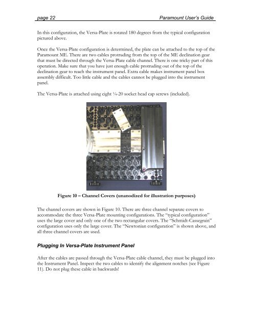
Figure 10 – Channel Covers (unanodized for illustration purposes)<br />
The channel covers are shown in Figure 10. There are three channel separate covers to<br />
accommodate the three Versa-Plate mounting configurations. The “typical configuration”<br />
uses the large cover and only one of the two rectangular covers. The “Schmidt-Cassegrain”<br />
configuration uses only the large cover. The “Newtonian configuration” is shown above, and<br />
all three channel covers are used.<br />
Plugging In Versa-Plate Instrument Panel<br />
After the cables are passed through the Versa-Plate cable channel, they must be plugged into<br />
the Instrument Panel. Inspect the two cables to identify the alignment notches (see Figure<br />
11). Do not plug these cable in backwards!