ZX Computings - OpenLibra
ZX Computings - OpenLibra
ZX Computings - OpenLibra

Create successful ePaper yourself
Turn your PDF publications into a flip-book with our unique Google optimized e-Paper software.
int it on the<br />
a piece of<br />
iuble-sided<br />
gsof the IC<br />
Js, and do<br />
with the<br />
ily conneci<br />
are to the<br />
;hown. The<br />
ORAM CS<br />
»rneath the<br />
appears on<br />
pad 2A. We<br />
mection to<br />
ne and two!<br />
:ted to the<br />
id 2A. Tl<br />
ick leading<br />
jin eight of<br />
Pick a spot<br />
j track an<<br />
ts about ar<br />
>art, using i<br />
till using the<br />
away all ol<br />
n, so there is<br />
jtween the<br />
ire from pill<br />
;topineighi<br />
itted or not<br />
the 7400 IC<br />
ble without<br />
f track. At<br />
+ 5 volt wire<br />
jpacitor C9<br />
let them the<br />
he onty wirf<br />
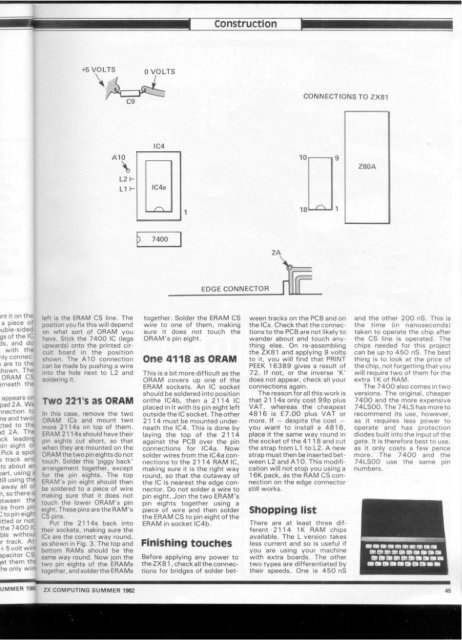
+5 VOLTS 0 VOLTS<br />
left is the ERAM CS line. The<br />
position you fix this will depend<br />
on what sort of ORAM you<br />
have. Stick the 7400 IC (legs<br />
upwards) onto the printed circuit<br />
board in the position<br />
shown. The A10 connection<br />
can be made by pushing a wire<br />
into the hole next to L2 and<br />
soldering it.<br />
TWO 221S as ORAM<br />
In this case, remove the two<br />
ORAM ICs and mount two<br />
more 2114s on top of them.<br />
ER AM 2114s should have their<br />
pin eights cut short, so that<br />
when they are mounted on the<br />
ORAM the two pin eights do not<br />
touch. Solder this 'piggy back'<br />
arrangement together, except<br />
for the pin eights. The top<br />
ERAM's pin eight should then<br />
be soldered to a piece of wire<br />
making sure that it does not<br />
touch the lower ORAM'S pin<br />
eight. These pins are the RAM's<br />
CS pins.<br />
Put the 2114s back into<br />
their sockets, making sure the<br />
ICs are the correct way round,<br />
as shown in Fig. 3. The top and<br />
bottom RAMs should be the<br />
same way round. Now join the<br />
two pin eights of the ERAMs<br />
together, and solder the ERAMs<br />
IC4<br />
) 7400<br />
Construction<br />
EDGE CONNECTOR<br />
together. Solder the ERAM CS<br />
wire to one of them, making<br />
sure it does not touch the<br />
ORAM'S pin eight.<br />
One 4118 as ORAM<br />
This is a bit more difficult as the<br />
ORAM covers up one of the<br />
ERAM sockets. An IC socket<br />
should be soldered into position<br />
onthe IC4b, then a 2114 IC<br />
placed in it with its pin eight left<br />
outside the IC socket. The other<br />
2114 must be mounted underneath<br />
the IC4, This is done by<br />
laying the top of the 2114<br />
against the PCB over the pin<br />
connections for IC4a, Now<br />
solder wires from the IC4a connections<br />
to the 21 1 4 RAM IC,<br />
making sure it is the right way<br />
round, so that the cutaway of<br />
the IC is nearest the edge connector.<br />
Do not solder a wire to<br />
pin eight. Join the two ERAM's<br />
pin eights together using a<br />
piece of wire and then solder<br />
the ERAM CS to pin eight of the<br />
ERAM in socket IC4b.<br />
Finishing touches<br />
Before applying any power to<br />
the <strong>ZX</strong>81, check all the connections<br />
for bridges of solder bet-<br />
T<br />
J<br />
CONNECTIONS TO <strong>ZX</strong>81<br />
ween tracks on the PCB and on<br />
the tCs. Check that the connections<br />
to the PCB are not likely to<br />
wander about and touch anything<br />
else. On re-assembling<br />
the <strong>ZX</strong>81 and applying 9 volts<br />
to it, you will find that PRINT<br />
PEEK 16389 gives a result of<br />
72. (f not, or the inverse 'K'<br />
does not appear, check all your<br />
connections again.<br />
The reason for all this work is<br />
that 2114s only cost 99p plus<br />
VAT, whereas the cheapest<br />
4816 is £7.00 plus VAT or<br />
more. If — despite the cost —<br />
you want to install a 4816,<br />
place it the same way round in<br />
the socket of the 4118 and cut<br />
the strap from L1 to L2. A new<br />
strap must then be inserted between<br />
L2 and A10. This modification<br />
will not stop you using a<br />
16K pack, as the RAM CS connection<br />
on the edge connector<br />
still works.<br />
Shopping list<br />
There are at least three different<br />
2114 1 K RAM chips<br />
available. The L version takes<br />
less current and so is useful if<br />
you are using your machine<br />
with extra boards. The other<br />
two types are differentiated by<br />
their speeds. One is 450 nS<br />
and the other 200 nS. This is<br />
the time (in nanoseconds)<br />
taken to operate the chip after<br />
the CS line is operated. The<br />
chips needed for this project<br />
can be up to 450 nS. The best<br />
thing is to look at the price of<br />
the chip, not forgetting that you<br />
will require two of them for the<br />
extra 1K of RAM.<br />
The 7400 also comes in two<br />
versions. The original, cheaper<br />
7400 and the more expensive<br />
74LS00. The 74LS has more to<br />
recommend its use, however,<br />
as it requires less power to<br />
operate and has protection<br />
diodes built into the input of the<br />
gate. It is therefore best to use,<br />
as it only costs a few pence<br />
more. The 7400 and the<br />
74LS00 use the same pin<br />
numbers.<br />
UMMER 19S <strong>ZX</strong> COMPUTING SUMMER 1982 45