ZX Computings - OpenLibra
ZX Computings - OpenLibra
ZX Computings - OpenLibra

You also want an ePaper? Increase the reach of your titles
YUMPU automatically turns print PDFs into web optimized ePapers that Google loves.
Hardware<br />
DCP<br />
M icr odevelopments<br />
Packs<br />
The Basic V Pack<br />
This is 4K of dynamic RAM (2 x<br />
6116s) to add to the basic 1K<br />
provided with the machine.<br />
This gives a total of 5K, the<br />
maximum amount of memory<br />
allowed by the system. It also<br />
provides separate input and<br />
output ports at the back of the<br />
'P' pack which are memory<br />
mapped. Because the port is<br />
memory mapped, it can be<br />
PEEKed and POKEd to get information<br />
to and from the computer.<br />
It makes no difference if<br />
the computer is a <strong>ZX</strong>80 or a<br />
<strong>ZX</strong>81 and it will work with a 4K<br />
or 8K ROM. It is not possible to<br />
connect anything else to the<br />
computer without using a<br />
motherboard as the only other<br />
connectors on the 'P' pack are<br />
0.1 molex pins for the port.<br />
These pins are about % inch<br />
long and there are 10 for input<br />
and 10 for output. The pins are<br />
connected to the eight data<br />
lines and also provide + 5 and 0<br />
volts. They can only drive one<br />
TTL gate from each output pin.<br />
The ports address is anywhere<br />
from 21504 to 22527<br />
as the single port replaces 1K of<br />
RAM. The plug connections<br />
used for the port are readily<br />
available from other sources<br />
than DCP.<br />
The port can be demonstrated<br />
by the use of switches<br />
Stephen Adams takes a peek and<br />
a poke inside this system which<br />
is based on a single input/<br />
output port and intended for a<br />
wide range of educational and<br />
control applications. It can be<br />
used — with the other packs<br />
available to plug into the port —<br />
to monitor heatf light and<br />
voltage, as well as activating<br />
alarms and motors, and making<br />
sounds.<br />
and LEDs. A suitable circuit<br />
diagram is included in the leaflet<br />
that comes with the port. It is<br />
very easy to use and comes in a<br />
robust black plastic box 3)4 *<br />
3% x 1% inches. Demonstration<br />
programs are given, and<br />
with the accompanying information<br />
any user should find it<br />
easy.<br />
This is a basic building block<br />
for DCP's control system and<br />
although it provides only 5K of<br />
memory, this should be more<br />
than enough to control most<br />
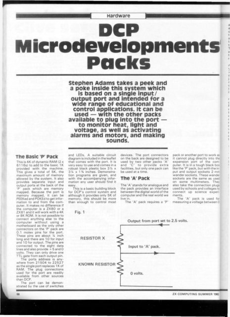
Fig. 1<br />
RESISTOR X<br />
KNOWN RESISTOR<br />
devices. The port connectors<br />
on the back are designed to be<br />
used by two other packs 'A'<br />
and 'C' to provide extra<br />
facilities, but only one pack can<br />
be used at a time.<br />
The A' Pack<br />
The 'A' stands for analogue and<br />
the pack provides an interface<br />
between the digital world of the<br />
computer and the real world we<br />
live in.<br />
The 'A' pack requires a 'P'<br />
Output from port set to 2.5 volts.<br />
Input to 'A' pack.<br />
0 volts.<br />
pack or another port to work as<br />
it cannot plug directly into tN<br />
expansion port of the computer.<br />
It is in a tough black bo*<br />
like the 'P' pack, but with the input<br />
and output sockets 2 mm<br />
wander sockets. These wander<br />
sockets are the same as used<br />
on some multimeters. They<br />
also take the connection plugs<br />
used by schools and colleges to<br />
connect up science experiments.<br />
The 'A' pack is used for<br />
measuring a voltage between 0<br />
<strong>ZX</strong> COMPUTING SUMMER 1982<br />
a •<br />
c<br />
t<br />
a