

1993_Motorola_Linear_Interface_ICs_Vol_2.pdf
1993_Motorola_Linear_Interface_ICs_Vol_2.pdf
1993_Motorola_Linear_Interface_ICs_Vol_2.pdf

You also want an ePaper? Increase the reach of your titles
YUMPU automatically turns print PDFs into web optimized ePapers that Google loves.
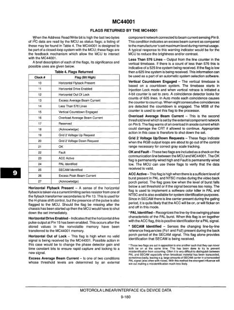
When the Address Read/Write bit is high the last two bytes<br />
of 12C data are read by the MCU as status flags; a listing of<br />
these may be found in Table 4. The MC44001 is designed to<br />
be part of a closed-loop system with the MCU; these flags are<br />
the feedback mechanism which allow the MCU to interact<br />
with the MC44001.<br />
A brief description of each of the flags, its significance and<br />
possible uses are given below.<br />
Table 4. Flags Returned<br />
Clock # Flag (Bit High)<br />
10 Horizontal Flyback Present<br />
11 Horizontal Drive Enabled<br />
12 Horizontal Out Of Lock<br />
13 Excess Average Beam Current<br />
14 Less Than 576 Lines<br />
15 Vertical Countdown Engaged<br />
16 Overload Average Beam Current<br />
17 Reserved<br />
18 (Acknowledge)<br />
19 Grid 2 <strong>Vol</strong>tage Up Request<br />
20 Grid 2 <strong>Vol</strong>tage Down Request<br />
21 OK<br />
22 Fault<br />
23 ACC Active<br />
24 PAL Identified<br />
25 SECAM Identified<br />
26 Excess Peak Beam Current<br />
27 (Acknowledge)<br />
Horizontal Flyback Present - A sense of the horizontal<br />
flyback is taken via a current limiting series resistor from one of<br />
the flyback transformer secondaries to Pin 13. This is used for<br />
the H-phase shift control, but the presence of the pulse is also<br />
flagged to the MCU. Should the flag be missing after the<br />
chassis has been started up then the MCU would have to shut<br />
down the set immediately.<br />
Horizontal Drive Enabled -Indicates that the horizontal drive<br />
pulse output at Pin 15 has been enabled. This occurs after the<br />
stored values in the nonvolatile memory have been<br />
transferred to the MC44001 memory.<br />
Horizontal Out of Lock - This flag is high when no valid<br />
signal is being received by the MC44001. Possible action in<br />
this case would be to change the phase detector gain and<br />
time constant bits to ensure rapid capture and locking to a<br />
new signal.<br />
Excess Average Beam Current - Is one of two conditions<br />
whose threshold levels are determined by an external<br />
MC44001<br />
FLAGS RETURNED BY THE MC44001<br />
MOTOROLA LINEAR/INTERFACE <strong>ICs</strong> DEVICE DATA<br />
9-180<br />
component network connected to beam current sensing Pin 9.<br />
This condition indicates an excess beam current as compared<br />
tothe manufacturer's set maximum level during normal usage.<br />
A typical response to this warning indicator would be for the<br />
MCU to reduce the brightness and/or contrast.<br />
Less Than 576 Lines - Output from the line counter in the<br />
vertical timebase. If there is a count of less than 576 this is<br />
indicative of a 525 line system being received. If the flag is low<br />
then a 625 line system is being received. This information can<br />
be used as a part of an automatic system selection software.<br />
Vertical Countdown Engaged - The vertical time base is<br />
based on a countdown system. The timebase starts in<br />
Injection Lock mode and when vertical retrace is initiated a<br />
4-bit counter is set to zero. A coincidence detector looks for<br />
counts of 625 lines. In Auto mode each coincidence causes<br />
the counter to count up. When eight consecutive coincidences<br />
are detected the countdown is engaged. The MSB of the<br />
counter is used to set this flag to the processor.<br />
Overload Average Beam Current - This is the second<br />
threshold level which is set by the external component network<br />
on Pin 9. The flag warns of an overload in anode current which<br />
could damage the CRT if allowed to continue. Appropriate<br />
action in this case is therefore to shut down the set.<br />
Grid 2 <strong>Vol</strong>tage Up/Down Requests - These flags indicate<br />
when the RGB output loops are about to go out of the control<br />
range necessary for correct gray scale tracking.<br />
OK and Fault-These two flags are included as a check on the<br />
communication line between the MCU and MC44001. The OK<br />
flag is permanently wired high and Fault is permanently wired<br />
low. The MCU can use these flags to verify that the data<br />
received is valid.<br />
ACC Active-This flag is high when there is a sufficient level of<br />
burst present in PAL and NTSC modes during the video back<br />
porch period. The flag goes low when the level of burst falls<br />
below a set threshold or if the signal becomes too noisy. The<br />
flag is used to implement a software color killer in PAL and<br />
NTSC and is also available for system identification purposes.<br />
Since in SECAM there is line carrier present during the gating<br />
period, it is quite likely that the ACC will be on, or will flicker on<br />
and off in this mode.<br />
• PAL Identified - Recognizes the line-by-line swinging phase<br />
characteristic of the PAL burst. When this flag is on together<br />
with the ACC flag, this is positive identification for a PAL Signal.<br />
• SECAM Identified - Senses the changing line-by-line<br />
reference frequencies (F01 and F02) present during the back<br />
porch period of the SECAM signal. This flag alone provides<br />
identification that SECAM is being received.<br />
• These two flags are set in opposition to one another such that they can never<br />
both be on at the same time. This has been done to try to prevent<br />
misidentification from occurring. Often it is very difficult to distinguish between<br />
PAL and SECAM especially when broadcast material has been transcoded,<br />
sometimes badly. leaving e.g. large amounts of SECAM carrier in a transcoded<br />
PAL signal (also often with noise). With this method the strongest influence will<br />
win out making a misidentification much less likely.


