1747-6.5.5, SL 500 DeviceNet Scanner Module User Manual
1747-6.5.5, SL 500 DeviceNet Scanner Module User Manual
1747-6.5.5, SL 500 DeviceNet Scanner Module User Manual

Create successful ePaper yourself
Turn your PDF publications into a flip-book with our unique Google optimized e-Paper software.
2-4 Planning Your Configuration and Data Mapping Your Devices<br />
Publication <strong>1747</strong>-<strong>6.5.5</strong> - August 2000<br />
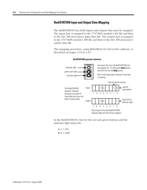
RediSTATION Input and Output Data Mapping<br />
The RediSTATION has both inputs and outputs that must be mapped.<br />
The input byte is mapped to the <strong>1747</strong>-SDN module’s M1 file and then<br />
to the <strong>SL</strong>C <strong>500</strong> processor’s input data file. The output byte is mapped<br />
to the <strong>1747</strong>-SDN module’s M0 file and then to the <strong>SL</strong>C <strong>500</strong> processor’s<br />
output data file.<br />
The mapping procedure, using RSNetWorx for <strong>DeviceNet</strong> software, is<br />
described on pages 4-12 to 4-15.<br />
In the RediSTATION’s bits for the red and green buttons and the<br />
indicator light status bit:<br />
• 1 = ON<br />
• 0 = OFF<br />
Indicator light<br />
green start light<br />
red start light<br />
RediSTATION operator interface<br />
The RediSTATION<br />
operator interface<br />
produces one byte of<br />
input data and uses one<br />
byte of output data.<br />
input<br />
output<br />
Two input bits from the RediSTATION will<br />
be mapped: bit 1 for the green Start button<br />
and bit 0 for the red Stop button.<br />
Bit 4 of the input byte indicates if the bulb<br />
is missing.<br />
1 byte<br />
1 byte<br />
start bit (green button)<br />
G R<br />
7 6 5 4 3 2 1 0<br />
7 6 5 4 3 2 1 0<br />
One output bit for the RediSTATION’s<br />
indicator light (on/off) will be mapped.<br />
L<br />
stop bit<br />
(red button)<br />
status bit for<br />
indicator light