Advanced Wind Turbine Program Next Generation Turbine ... - NREL
Advanced Wind Turbine Program Next Generation Turbine ... - NREL
Advanced Wind Turbine Program Next Generation Turbine ... - NREL

Create successful ePaper yourself
Turn your PDF publications into a flip-book with our unique Google optimized e-Paper software.
2.3.1.1 Upwind Rotor Blade and Tower Flexibility<br />
Two different studies were commissioned by GE to investigate the impact of reducing the wind<br />
turbine rotor blade stiffness. Both studies were conducted using the baseline 750i turbine as the<br />
study control. The studies were conducted in slightly different ways, as explained below.<br />
In the first study, a model of the baseline 750i turbine using the baseline 48-m rotor was developed.<br />
A new “softer” blade was modeled with stiffness equal to 50% of the baseline value and<br />
mass reduced to roughly 70% of the baseline. Though softer, the blade is still stiff (above 2p). In<br />
addition to the baseline tower, a so-called “soft-soft” tubular tower with a first natural frequency<br />
less than the turbine main shaft maximum rotational rate was also modeled. Two towers and two<br />
rotor configurations yield four configurations for study.<br />
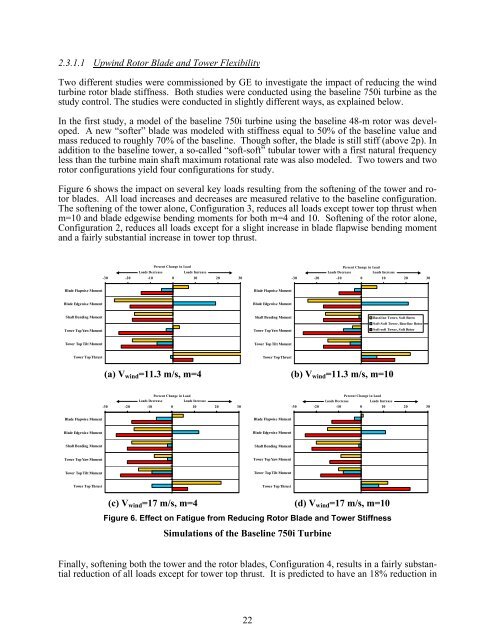
Figure 6 shows the impact on several key loads resulting from the softening of the tower and rotor<br />
blades. All load increases and decreases are measured relative to the baseline configuration.<br />
The softening of the tower alone, Configuration 3, reduces all loads except tower top thrust when<br />
m=10 and blade edgewise bending moments for both m=4 and 10. Softening of the rotor alone,<br />
Configuration 2, reduces all loads except for a slight increase in blade flapwise bending moment<br />
and a fairly substantial increase in tower top thrust.<br />
Blade Flapwis e Moment<br />
Blade Edgewise Moment<br />
Shaft Bending Moment<br />
Tower Top Yaw Moment<br />
Tower Top Tilt Moment<br />
Tower Top Thrust<br />
Blade Flapwis e Moment<br />
Blade Edgewise Moment<br />
Shaft Bending Moment<br />
Tower Top Yaw Moment<br />
Tower Top Tilt Moment<br />
Tower Top Thrust<br />
Percent Change in Load Percent Change in Load<br />
Loads Decrease Loads Increase Loads Decrease Loads Increase<br />
-30 -20 -10 0 10 20 30 -30 -20 -10 0 10 20 30<br />
Blade Flapwise Moment<br />
Blade Edgewise Moment<br />
Shaft Bending Moment<br />
Tower Top Yaw Moment<br />
Tower Top Tilt Moment<br />
Tower Top Thrust<br />
(a) Vwind=11.3 m/s, m=4 (b) Vwind=11.3 m/s, m=10<br />
Baseline Tower, S oft Rotro<br />
S oft-S oft Tower, Baseli ne Rotor<br />
S oft-soft Tower, S oft Rotor<br />
Percent Change in Load Percent Change in Load<br />
Loads Decrease Loads Increase Loads Decrease Loads Increase<br />
-30 -20 -10 0 10 20 30 -30 -20 -10 0 10 20 30<br />
Blade Flapwise Moment<br />
Blade Edgewise Moment<br />
Shaft Bending Moment<br />
Tower Top Yaw Moment<br />
Tower Top Tilt Moment<br />
Tower Top Thrust<br />
(c) Vwind=17 m/s, m=4 (d) Vwind=17 m/s, m=10<br />
Figure 6. Effect on Fatigue from Reducing Rotor Blade and Tower Stiffness<br />
Simulations of the Baseline 750i <strong>Turbine</strong><br />
Finally, softening both the tower and the rotor blades, Configuration 4, results in a fairly substantial<br />
reduction of all loads except for tower top thrust. It is predicted to have an 18% reduction in<br />
22